
Control device, power transmitting device, contactless power transmission system, power receiving device, and electronic apparatus

Active Publication Date: 2020-04-23
SEIKO EPSON CORP
View PDF0 Cites 5 Cited by
  • Summary
  • Abstract
  • Description
  • Claims
  • Application Information

AI Technical Summary

Benefits of technology

The control device described in this patent is used in a power transmitting device. It includes a power transmission driver that sends power to a power receiving device, which then uses the power to generate a rectified voltage. The control device also has a communication circuit that receives information about the rectified voltage. The control circuit then switches between a full-bridge drive mode and a half-bridge drive mode based on this information. The technical effect of this invention is that it allows for better control of the power transfer between devices, ultimately resulting in more efficient and reliable power transmission.

Problems solved by technology

When a primary coil on a power transmitting side is driven with a half-bridge configuration, in contactless power transmission, a problem arises in that, although excessive power is not transmitted even when a secondary coil comes close to the primary coil, it is disadvantageous with respect to the degree of positional freedom.
On the other hand, when the primary coil is driven with a full-bridge configuration, a problem arises in that, although the degree of positional freedom increases, when the secondary coil comes close to the primary coil, excessive power is transmitted, and excessive heat is generated.
With the method in JP-A-2014-54134, improvement of the degree of positional freedom and suppression of excessive heat generation cannot be achieved at the same time.

Method used


Image

  • Control device, power transmitting device, contactless power transmission system, power receiving device, and electronic apparatus
  • Control device, power transmitting device, contactless power transmission system, power receiving device, and electronic apparatus
  • Control device, power transmitting device, contactless power transmission system, power receiving device, and electronic apparatus

Examples


Embodiment Construction

[0023]Hereinafter, a preferable embodiment of the invention will be described in detail. Note that the embodiment described below is not intended to unduly limit the content of the invention described in the scope of the claims, and not all configurations described in this embodiment are necessarily essential as solving means of the invention.

1. Configuration

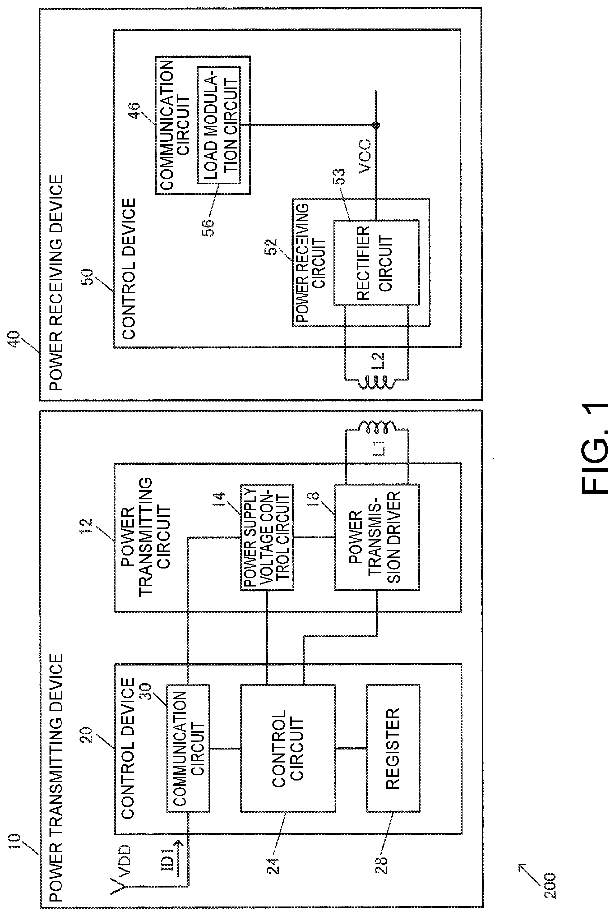
[0024]FIG. 1 shows an exemplary configuration of a control device 20 of the present embodiment and a power transmitting device 10 including the control device 20. A contactless power transmission system 200 is constituted by the power transmitting device 10 and a power receiving device 40. Note that the configuration of the control device 20 and the power transmitting device 10 of the present embodiment is not limited to the configuration in FIG. 1, and various modifications can be implemented such as omitting some of the constituent elements or adding other constituent elements.

[0025]The power transmitting device 10 includes a ...


PUM


Abstract

A control device controls a power transmission driver that transmits power to a power receiving device including a rectifier circuit that is connected to a secondary coil and generates a rectified voltage, by outputting a drive signal to a primary coil. The control device switches the drive mode of the power transmission driver between a full-bridge drive mode and a half-bridge drive mode according to the rectified voltage.

Description

[0001]The present application is based on, and claims priority from JP Application Serial Number 2018-196408, filed Oct. 18, 2018, the disclosure of which is hereby incorporated by reference herein in its entirety.BACKGROUND1. Technical Field[0002]The present disclosure relates to a control device, a power transmitting device, a contactless power transmission system, a power receiving device, an electronic apparatus, and the like.2. Related Art[0003]In recent years, much attention has been paid to contactless power transmission in which electromagnetic induction is used to make power transmission possible without a metal contact. Power supply to electronic apparatuses such as a household appliance, a mobile terminal, and an electric car has been proposed as an application example of the contactless power transmission.[0004]A known technology for the contactless power transmission is disclosed in JP-A-2014-54134, for example. In the technology disclosed in JP-A-2014-54134, the drive ...

Claims


Application Information

Patent Timeline
IPC IPC(8): H02J50/12H02J5/00H02J7/02H02J50/80
CPCH02J50/80H04B5/0093H02J5/005H04B5/0037H02J7/025H02J50/12H02J50/10H02J50/90H04B5/266H04B5/79
Inventor MATSUDA, KINYA
Owner SEIKO EPSON CORP
Learn More