Cutting machine

Active Publication Date: 2020-04-30
MAKITA CORP
View PDF0 Cites 3 Cited by
  • Summary
  • Abstract
  • Description
  • Claims
  • Application Information

AI Technical Summary

Benefits of technology

The present invention is about a cutting machine that is designed to reduce manufacturing costs associated with different types of batteries. Its flexible design allows it to be used for various types of batteries and helps to lower overall production costs.

Problems solved by technology

Cutting machines with such different batteries use different molds for their handles or motor housings, thus increasing the cost for production equipment.

Method used


Image

  • Cutting machine
  • Cutting machine
  • Cutting machine

Examples


Embodiment Construction

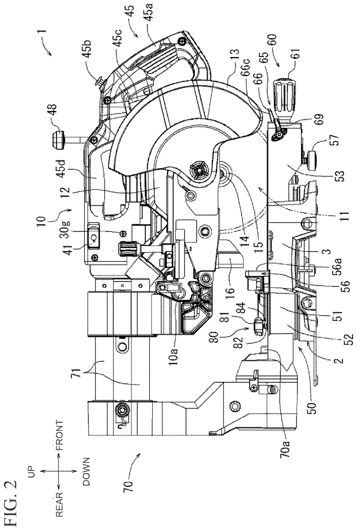
[0058]A cutting machine 1 will now be described with reference to FIGS. 1 to 37. The cutting machine (stationary tool) 1 according to the present embodiment is a sliding circular saw. As shown in FIG. 1, the cutting machine 1 includes a cutting machine body 10, a turntable 50 on which a workpiece is placeable, and a base 2. The base 2 is placed on a surface such as a table or a floor to support the turntable 50 in a manner rotatable horizontally. The base 2 includes auxiliary tables 3 on both the right and the left of the turntable 50. The auxiliary tables 3 have the same height at their upper surfaces as the turntable 50.

[0059]For components and structures described below, the directional terms such as up, down, right, and left are defined as seen from a user. The front and the rear of the members and components are defined as the front being closer to the user.

[0060]As shown in FIGS. 10 and 11, the turntable 50 is supported in a manner rotatable horizontally with respect to the ba...


PUM

PropertyMeasurementUnit
Sizeaaaaaaaaaa
Flexibilityaaaaaaaaaa
Shapeaaaaaaaaaa

Abstract

A cutting machine reduces cost increase associated with production equipment and has design flexibility for different types of batteries. A cutting machine for cutting a workpiece includes a cutting machine body including a cutting blade, a motor that drives the cutting blade, and a motor housing accommodating the motor, and an adapter including a body holder attached to the cutting machine body and a battery holder in which a battery to power the motor is installable.

Description

CROSS-REFERENCE TO RELATED APPLICATIONS[0001]This application claims the benefit of priority to Japanese Patent Application No. 2018-204184, filed on Oct. 30, 2018, the entire contents of which are hereby incorporated by reference.BACKGROUND1. Technical Field[0002]The present invention relates to a cutting machine, referred to as a sliding circular saw or a portable circular saw, mainly used for cutting wood.2. Description of the Background[0003]A cutting machine described in Japanese Unexamined Patent Application Publication No. 2017-213655 (hereafter, Patent Literature 1) includes a cutting machine body integrating a motor housing, a handle, and a battery holder. The motor housing accommodates a motor for driving a cutting blade. The handle is loop-shaped and thus grippable by a user. A battery to power the motor is removably installed in the battery holder. The cutting machine body is moved by operating the handle, with the cutting blade being driven by the motor. The cutting bla...

Claims


Application Information

Patent Timeline
IPC IPC(8): B23D47/12B23D45/14B23D45/04B27B5/29H01M2/10
CPCB27B5/29B23D45/042B23D45/14H01M2/1033B23D47/12B27B9/00B27B9/02B27G19/02B23D45/048B23D47/00H01M50/267
Inventor YOSHIDA, YUTOYAMAMURA, GOH
Owner MAKITA CORP
Why Eureka
Try Eureka