
Reconfigurable, fixtureless manufacturing system and method assisted by learning software

Active Publication Date: 2020-04-30
GHANEM GEORGE K
View PDF0 Cites 9 Cited by
  • Summary
  • Abstract
  • Description
  • Claims
  • Application Information

AI Technical Summary

Benefits of technology

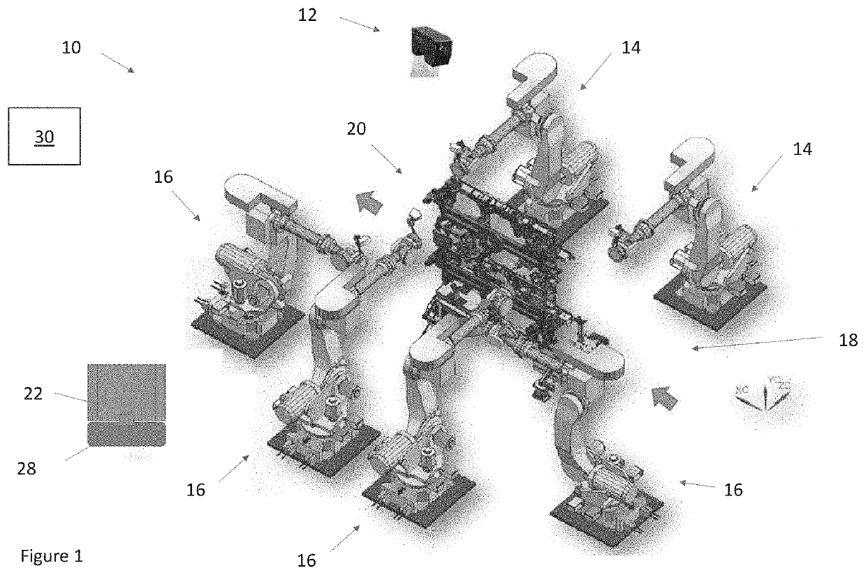
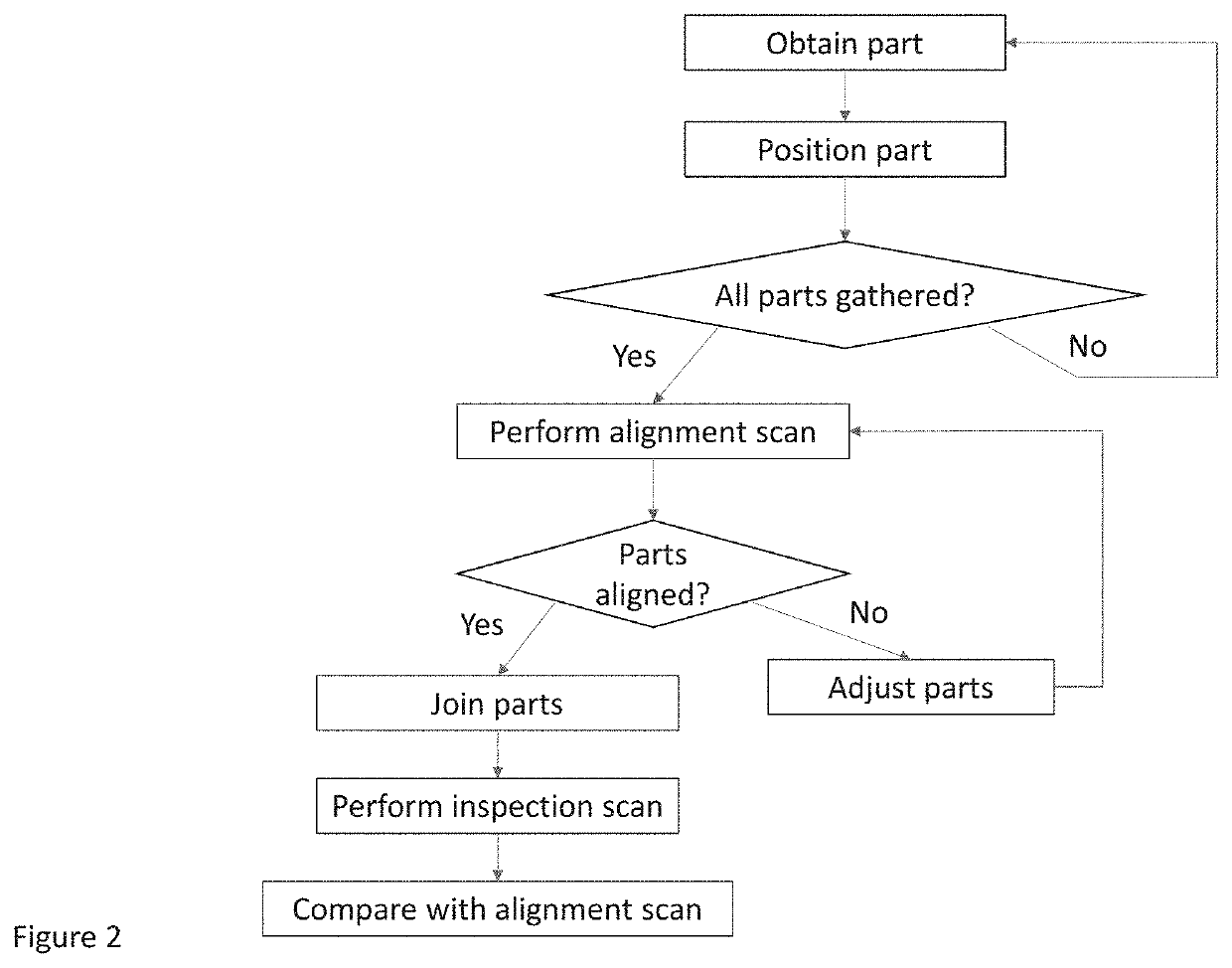
This patent describes a machine vision system that can inspect and align parts during the assembly process of a subassembly. The system captures the location of certain features or points on the parts and sends this information to a controller. The controller compares this information with pre-defined locations to determine the best fit of the parts and make adjustments for a better fit. The one or more joining robots then join the parts by welding, fastening, or riveting them. The machine vision system also inspects the completed subassembly and sends any discrepancies back to the controller for further adjustments. The system is flexible and can handle different parts, orientations, and shapes while optimizing the assembly process through multiple production cycles. Additionally, the system eliminates the need for physical fixtures and reduces the need for physical datum points.

Problems solved by technology

While some so-called flexible fixture systems are available, the costs of designing and manufacturing such flexible fixture systems are significant due to the complexity of design required to accommodate even minor changes.
Furthermore, even such flexible fixture systems may be quickly rendered obsolete upon the introduction of product changes.

Method used


Image

  • Reconfigurable, fixtureless manufacturing system and method assisted by learning software
  • Reconfigurable, fixtureless manufacturing system and method assisted by learning software
  • Reconfigurable, fixtureless manufacturing system and method assisted by learning software

Examples


Embodiment Construction

)

[0031]Various embodiments of the present invention will now be described in detail with reference to the accompanying drawings. In the following description, specific details such as detailed configuration and components are merely provided to assist the overall understanding of these embodiments of the present invention. Therefore, it should be apparent to those skilled in the art that various changes and modifications of the embodiments described herein can be made without departing from the scope and spirit of the present invention. In addition, descriptions of well-known functions and constructions are omitted for clarity and conciseness.

[0032]Embodiments of the invention are described herein with reference to illustrations of idealized embodiments (and intermediate structures) of the invention. As such, variations from the shapes of the illustrations as a result, for example, of manufacturing techniques and / or tolerances, are to be expected. Thus, embodiments of the invention ...


PUM


Abstract

Systems and methods for AI assisted reconfigurable, fixtureless manufacturing is disclosed. The invention eliminates geometry-setting tools (hard points, pins and nets—traditionally known as 3-2-1 fixturing schemes) and to replace the physical geometry setting with virtual datums driven by learning AI algorithms. A first type of part and a second type of part may be located by a machine vision system and moved by material handling devices and robots to locations within an assembly area. The parts may be aligned with one another and the alignment may be checked by the machine vision system which is configured to locate datums, in the form of features, of the parts and compare such datums to stored virtual datums. The parts may be joined while being held by the material handling devices or robots to form a subassembly in a fixtureless fashion. The material handling devices are able to grasp a number of different types of parts so that a number of different types of subassemblies are capable of being assembled. The system enables one skilled in the art to develop a product design with self-locating parts that will eliminate and minimize the need for geometry setting dedicated line tools and fixtures. This leads to the development of a manufacturing process that utilizes the industry 4.0 technologies to once again eliminate or significantly reduces the need for geometry setting line tools.

Description

CROSS-REFERENCE TO RELATED APPLICATIONS[0001]This application claims the benefit of U.S. Provisional Application Ser. No. 62 / 751,014 filed Oct. 26, 2018, the disclosures of which are hereby incorporated by reference as if fully restated.TECHNICAL FIELD[0002]Exemplary embodiments relate generally to a reconfigurable, fixtureless manufacturing system and method assisted by learning A.I. software.BACKGROUND AND SUMMARY OF THE INVENTION[0003]Dedicated hardware fixtures are often used to secure and locate sheet metal parts for welding. Such sheet metal parts may be welded together to create subassemblies, which may subsequently be used to make a larger product. A common example of where such processes are utilized is the automobile manufacturing industry. Regardless, a unique fixture must generally be designed and manufactured to accommodate each subassembly. While some so-called flexible fixture systems are available, the costs of designing and manufacturing such flexible fixture system...

Claims


Application Information

Patent Timeline
IPC IPC(8): B25J9/16G05B19/418
CPCB25J9/1612G05B2219/37567G05B2219/50125B25J9/1682G05B2219/50393B25J9/1697G05B19/41875B25J9/1687B25J9/163G05B2219/45064G05B2219/37555Y02P90/02
Inventor GHANEM, GEORGE K.
Owner GHANEM GEORGE K
Learn More