Electronic circuit for redundant supply of an electric load

Active Publication Date: 2020-04-30
APTIV TECH LTD
View PDF0 Cites 2 Cited by
  • Summary
  • Abstract
  • Description
  • Claims
  • Application Information

AI Technical Summary

Benefits of technology

[0009]The electronic circuit can be configured as an electronic module (optionally having a housing), wherein the first and second terminals are to be connected to the first and second energy sources, respectively. In contrast, the third terminal is connected to the load and can thus be regarded as an output terminal. As a general function, supply of the load should be enabled via the first energy source or the second energy source. However, the load should preferably not be supplied by both energy sources at the same time. In this way, a situation can be avoided in which both energy sources, which preferably are both batteries, are low, i.e. exhausted. In other words, the second energy source should preferably be configured as a back-up supply and should thus preferably not be in operation for supply of the electric load if the first energy is supplying. Furthermore, the circuit can be configured to disable power flow from the second energy source to the first energy source and/or vice versa, thereby avoiding a reverse flow of current between the energy sources.
[0010]The electronic circuit allows for a double-pairwise connection between two energy sources, thereby forming a ring structure. In such a configuration, the second terminals of a pair of two electronic circuits are interconnected and the first terminals of the electronic circuits are connected to a first energy source and a second energy source, respectively. Two of such pairs can be connected in parallel, thereby forming the ring (or part of a ladder structure). This allows for a significant reduction of the wiring because the second terminals do not need to be directly connected to the energy sources. Instead, supply of an electric load via a second terminal can be accomplis

Problems solved by technology

In many applications uninterrupted and sufficient supply of one or more electrical loads is required for safety reasons.
Insufficient supply of the control module needs to be avoided with maximum certainty since failure of the control module can lead to accidents including harm of passengers.
Insufficient supply of the electric load can be due to various errors, i.e.

Method used


Image

  • Electronic circuit for redundant supply of an electric load
  • Electronic circuit for redundant supply of an electric load
  • Electronic circuit for redundant supply of an electric load

Examples


Embodiment Construction

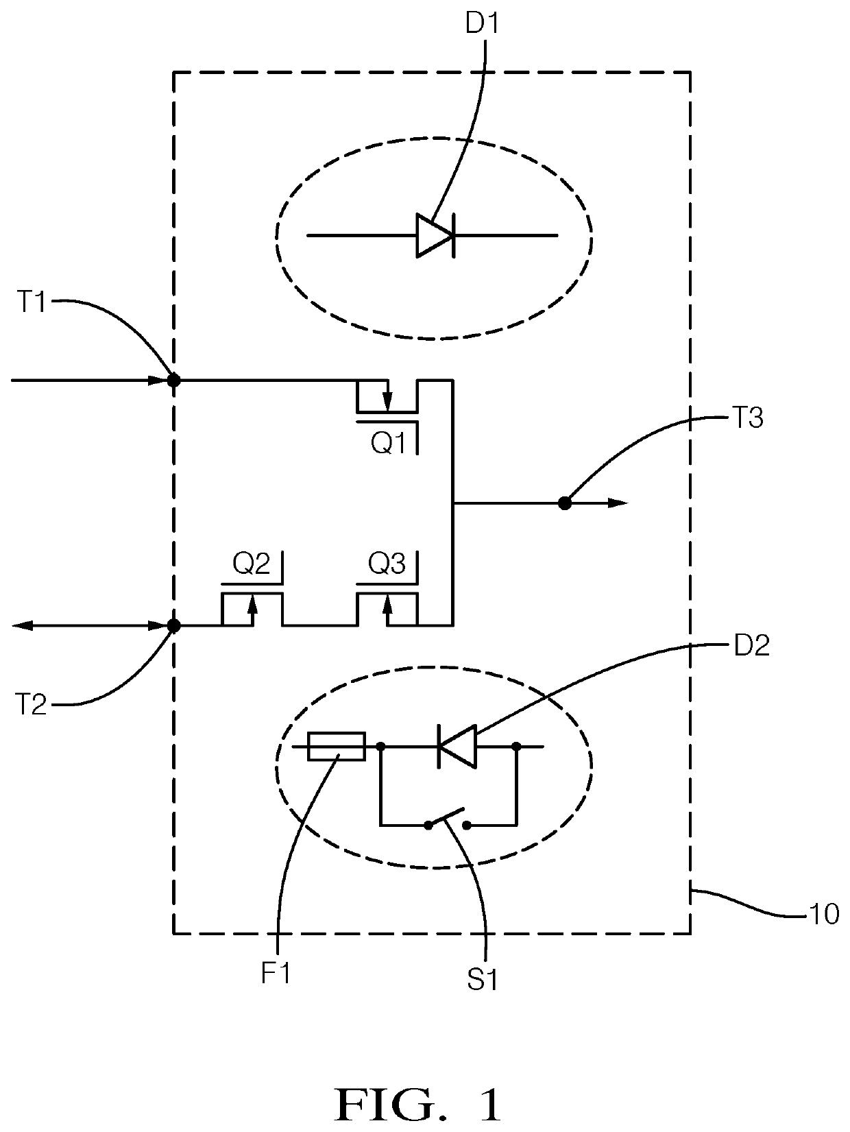
[0033]FIG. 1 schematically shows an electronic circuit 10 indicated by dashed lines, wherein the circuit 10 can be configured as an electronic module having a housing (not shown). The circuit 10 comprises a first terminal T1, a second terminal T2 and a third terminal T3. The terminals T1, T2, T3 can be configured as harnesses or generally so as to allow for a pin connection, e.g. by sockets cooperating with plugs or the like. Therefore, the terminals T1, T2, T3 can be regarded as electrical interfaces of the circuit 10.

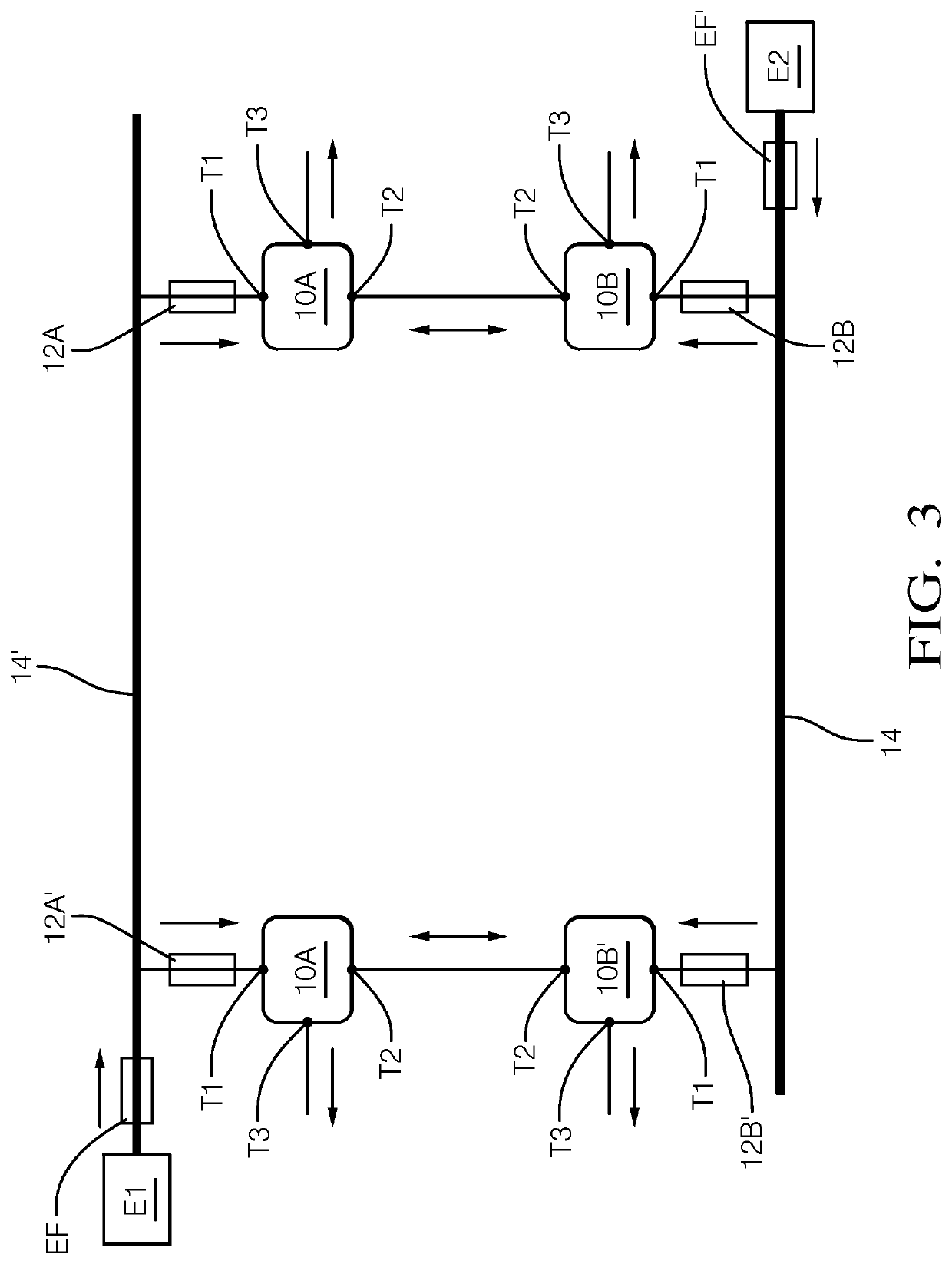
[0034]In FIG. 3, the third terminal T3 is located inside the circuit 10 so as to indicate that if the circuit 10 has a housing and / or is configured as a module (not shown) then the third terminal T3 is preferably not accessible from outside. In this case, the electric load can also be located inside the housing, wherein only the first and second terminals T1, T2 are accessible from outside in order to ensure redundant supply of the load. The circuit 10 can thus be int...


PUM


Abstract

An electronic circuit for redundant supply of an electric load comprises a plurality of terminals including at least a first terminal, a second terminal and at least one third terminal, wherein the first terminal is configured to be connected to a first energy source for primary supply of the electric load; the second terminal is configured to be connected to a second energy source for secondary supply of the electric load; the at least one third terminal is configured to be connected to the electric load; the electronic circuit further comprises a plurality of electrical components interposed between the first terminal, the second terminal and the at least one third terminal, the electrical components being configured to enable power flow from either the first terminal or the second terminal to the at least one third terminal in dependence of an erroneous supply state for the electric load.

Description

CROSS-REFERENCE TO RELATED APPLICATION[0001]This application claims the benefit under 35 U.S.C. § 119(a) of European Patent Application EP 18203854.7, filed Oct. 31, 2018, the entire disclosure of which is hereby incorporated herein by reference.TECHNICAL FIELD OF INVENTION[0002]The invention refers to an electronic circuit for redundant supply of an electric load.BACKGROUND OF INVENTION[0003]In many applications uninterrupted and sufficient supply of one or more electrical loads is required for safety reasons. One such application is in vehicles configured for autonomous driving. The electrical load can be for example a control module configured to carry out a processing task in connection with an autonomous driving feature. Insufficient supply of the control module needs to be avoided with maximum certainty since failure of the control module can lead to accidents including harm of passengers.[0004]Insufficient supply of the electric load can be due to various errors, i.e. erroneo...

Claims


Application Information

Patent Timeline
IPC IPC(8): H02J9/06
CPCH02J9/061H02J9/06G06F1/263G06F1/30G06F11/2015H02J1/10H02J7/34B60L2260/32B60L3/0092B60L3/0046B60L3/00B60R16/04
Inventor HEINRICH, MARKUS
Owner APTIV TECH LTD
Why Eureka
Try Eureka