Methods and systems for wavelength mapping cardiac fibrillation and optimizing ablation lesion placement
Active Publication Date: 2020-05-07
UNIVERSITY OF VERMONT
View PDF0 Cites 5 Cited by
- Summary
- Abstract
- Description
- Claims
- Application Information
AI Technical Summary
Benefits of technology
[0018]In some embodiments, different strategies for optimizing the placement of ablation lesion are analyzed. In some embodiments, a region capable of supporting stationary rotors is identified and quarantined with ablation lesion. Then, the system/process defines the optimal placement of other ablation lesion based on the identified stationary rot
Problems solved by technology
For instance, the prior ablation art fails to recognize the importance of, and provide methods and systems for, gauging a patient's fibril
Method used
View moreImage
Smart ImageViewing Examples

Examples
 PUM
 Abstract
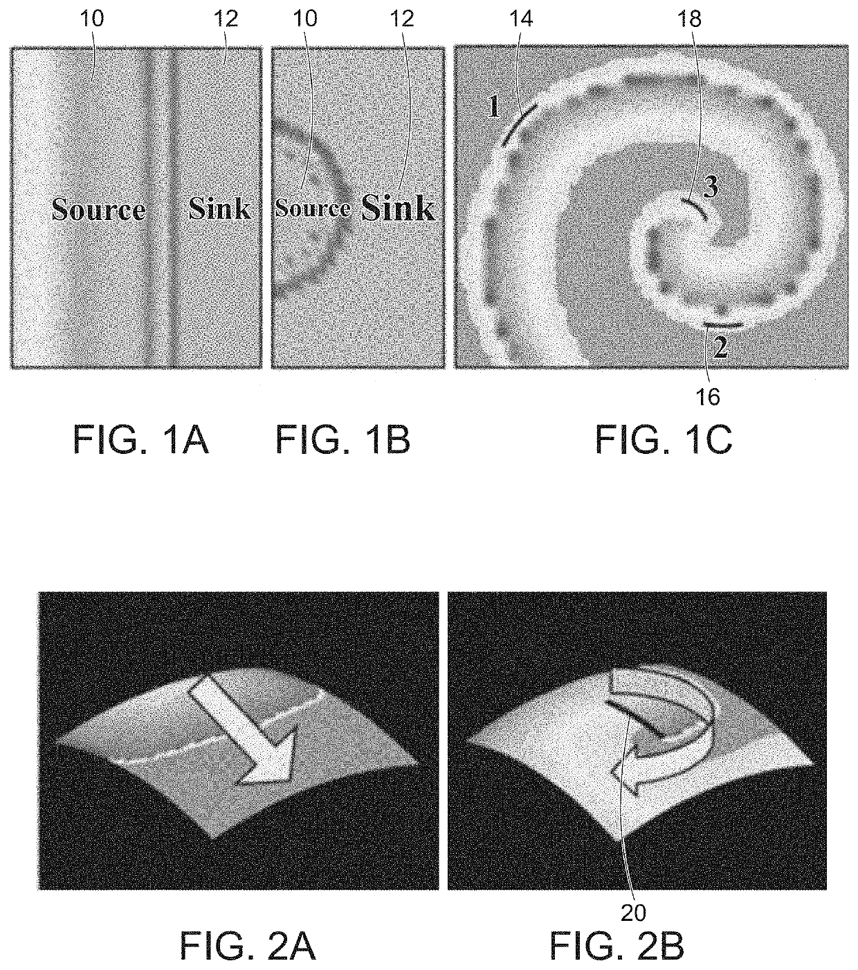
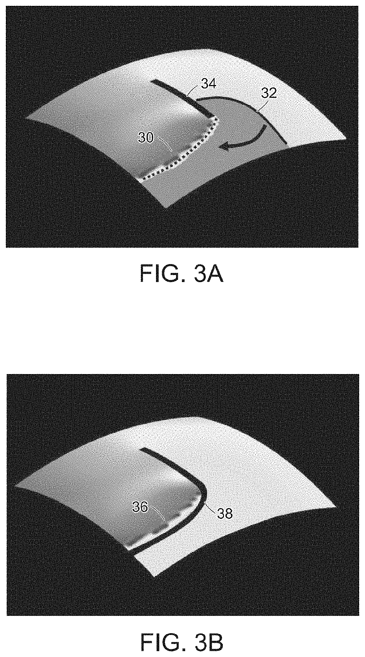
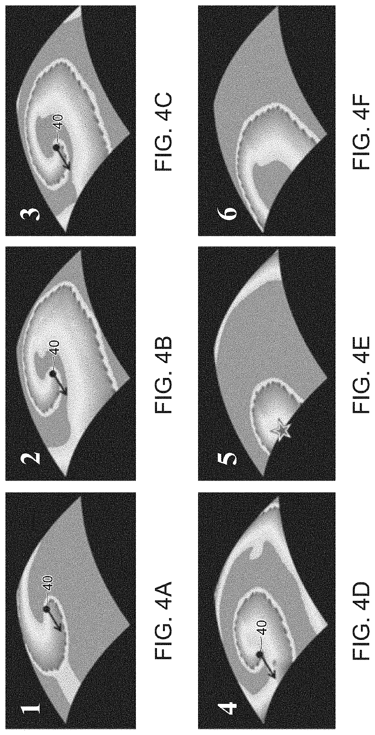
A system that executes a process for mapping cardiac fibrillation and optimizing ablation treatments. The process, in some embodiments, includes: positioning a two dimensional electrode array to several locations in a patient's heart and at each location, obtaining a conduction velocity and a cycle length measurement from at least two local signals in response to electrical activity in the cardiac tissue. In some embodiments, a regional wavelength is calculated by multiplying the local conduction velocity with the local minimum cycle length. The system can then create a wavelength distribution map that identifies the location of the drivers in the heart. In certain embodiments, the system uses variability of conduction velocity and cycle length in an area to determine the driver type. In some embodiments, the system calculates average distance of drivers to non-conductive tissue boundaries. The system then selects ablation placements that maximize treatment efficacy while minimizing tissue damage.
Description
RELATED APPLICATIONS[0001]This application is a continuation-in-part of U.S. patent application Ser. No. 15 / 627,013, filed on Jun. 19, 2017, which is a continuation of U.S. patent application Ser. No. 13 / 844,753, filed on Mar. 15, 2013, which claims the benefit of the filing date of U.S. Provisional Patent Application No. 61 / 753,387, filed on Jan. 16, 2013, the contents which are hereby incorporated by reference in their entireties. This application claims the benefit under 35 U.S.C. 119(e) to U.S. Provisional Application No. 62 / 773,713, entitled “Using Wavelength to Map Atrial Fibrillation,” which was filed on Nov. 30, 2018, the entire contents of which are incorporated herein by reference.TECHNICAL FIELD[0002]The present disclosure relates generally to methods and systems for detecting and treating cardiac fibrillation. More specifically, the present disclosure relates to physiologic, particularly electrophysiologic, methods and systems for preventing, treating, and at least minim...
Claims
Login to view more Application Information
Patent Timeline
 IPC IPC(8): A61B5/04A61B18/14A61B5/046A61B5/042A61B5/361
CPCA61B5/04017A61B34/20A61B5/046A61B18/1492A61B2034/2051A61B18/14A61B2017/00053A61B2562/046A61B5/0422A61B5/04014A61B2018/00839A61B2018/0016A61B5/316A61B5/287A61B5/361
Inventor SPECTOR, PETER S.
Owner UNIVERSITY OF VERMONT
- R&D Engineer
- R&D Manager
- IP Professional
Why Eureka
- Industry Leading Data Capabilities
- Powerful AI technology
- Patent DNA Extraction
Try Eureka
Browse by: Latest US Patents, China's latest patents, Technical Efficacy Thesaurus, Application Domain, Technology Topic.
© 2024 PatSnap. All rights reserved.Legal|Privacy policy|Modern Slavery Act Transparency Statement|Sitemap