
Raised pavement marker detector

Inactive Publication Date: 2020-05-14
PURUCZKY VINCENT
View PDF10 Cites 3 Cited by
  • Summary
  • Abstract
  • Description
  • Claims
  • Application Information

AI Technical Summary

Benefits of technology

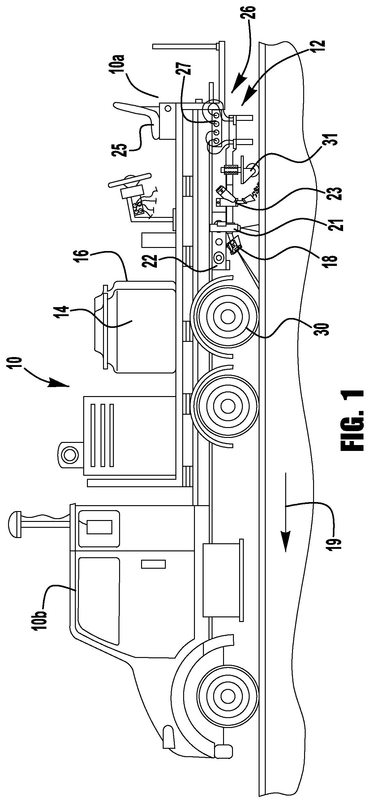
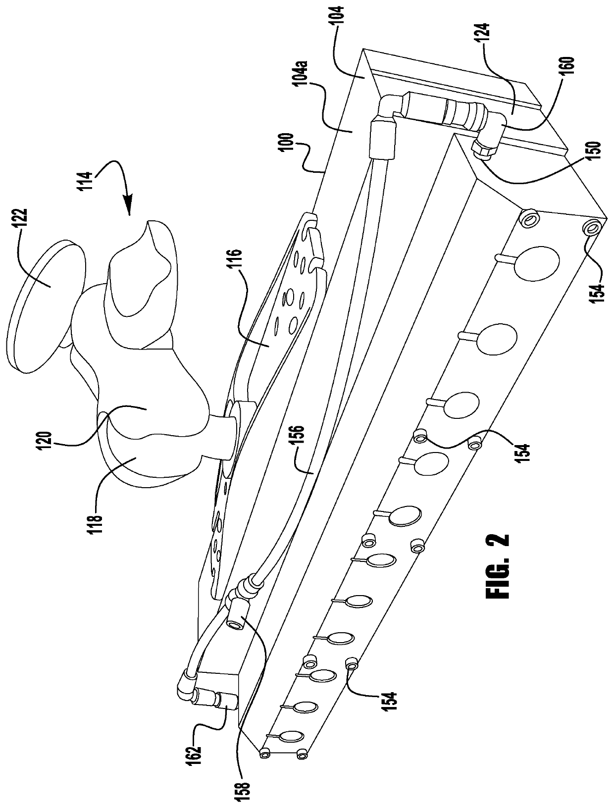
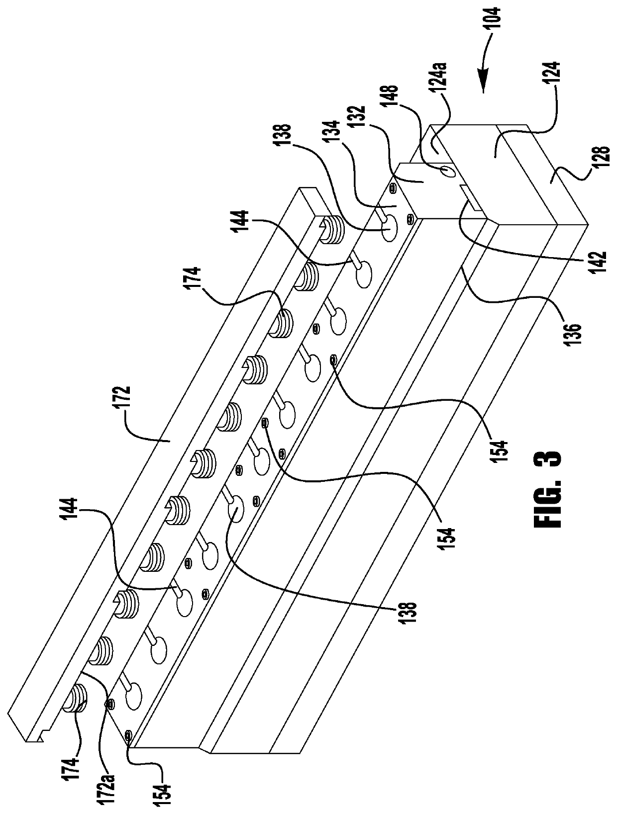
The present invention is about a device that detects when someone tries to paint raised markers on a road. The device is designed to be attached to a truck that carries paint. It has a housing that contains sensors that reflect light that is emitted from the device. The sensors are protected by a cover. The device also has a front body with openings that match the ones in the rear body, allowing the sensors to detect the markers. The technical effect of this invention is to make it easier to detect and paint raised markers on roads, which can help improve safety and efficiency.

Problems solved by technology

During this procedure, RPM's may be encounter that are situated directly within the center lines and if painted over will lose their reflectivity properties.
This method has proved faulty as other metal remnants within the road construction or garbage on top of the road surface can trigger the guns to be shut off at inappropriate times. This type of detector is positioned very close to the road which puts it at risk for being damaged from cracks or potholes in the pavement.
In addition, this method is unusable in areas where the RPMs are not encased in the metal casting.
This method is ineffective because of human error in judging exactly when to switch off the guns as the RPM approaches the raised pavement marker and when to turn the guns back on so as to not avoid a larger gap than required by the state specifications.
This method can also ineffective due to human error caused because the constant toggling of the guns between the on / off condition can also be monotonous in areas where the RPMs are more frequent.

Method used


Image

  • Raised pavement marker detector
  • Raised pavement marker detector
  • Raised pavement marker detector

Examples


Embodiment Construction

[0020]In the description that follows, numerous details are set forth in order to provide a thorough understanding of the present invention. It will be appreciated by those skilled in the art that variations of these specific details are possible while still achieving the results of the present invention. Well-known processing steps are generally not described in detail in order to avoid unnecessarily obfuscating the description of the present invention.

[0021]In the description that follows, exemplary dimensions may be presented for an illustrative embodiment of the invention. The dimensions should not be interpreted as limiting. They are included to provide a sense of proportion. Generally speaking, it is the relationship between various elements, where they are located, their contrasting compositions, and sometimes their relative sizes that is of significance.)

[0022]In the drawings accompanying the description that follows, often both reference numerals and legends (labels, text d...


PUM


Abstract

A raised pavement marker detector on a paint truck to detect the interruption of line striping for raised pavement markers, including a housing attached by a bracket to a carriage of the truck. The housing includes a rear shaped body having a first plurality of openings extending therethrough. Each of the first plurality of openings contains a retro reflector sensor and each sensor has a housing containing a transmitter and a receiver. A rear cover closes the first plurality of openings through the rear shaped body to protect the sensors. A front body contains a second plurality of openings extending therethrough and mounted to the rear shaped body whereby the second plurality of openings extending through the front body overlaps the first plurality of openings through the rear rectangular shaped body so as to receive a lens portion of each retro reflector sensor within the first plurality of openings.

Description

FIELD OF INVENTION[0001]The present invention relates generally to a detector to sense raised pavement markingsBACKGROUND OF INVENTION[0002]There are different types of marking materials used on roadways to direct traffic flow. To be visible to drivers during the night, retro-reflective materials are used. A retro-reflector is a device or surface that reflects light back to its source with a minimum of scattering.[0003]There are two (2) types of retroreflective materials used on roadways. There are the spherical glass beads incorporated with the paint marking application and there are the reflective prisms used in road signs and also in raised pavement markings. This invention is concerned with the raised pavement markings.[0004]There are many different styles of raised pavement markings (RPM's). There are those that are installed directly onto the pavement with an epoxy and others are recessed into the pavement either independent or encased within a casting currently made of cast i...

Claims


Application Information

Patent Timeline
IPC IPC(8): G01J1/02E01C23/22E01C23/01G01J1/42
CPCG01J1/0271E01C23/01E01C23/222G01J1/4228E01C23/163G01J1/0411
Inventor PURUCZKY, VINCENT
Owner PURUCZKY VINCENT
Learn More