
Hand worn interface device

a technology of interface device and hand, which is applied in the field of hand-worn interface device, can solve the problems of display hysteresis, value measurement change with temperature, and relatively high overall cos

Pending Publication Date: 2020-05-14
PLEXUS IMMERSIVE CORP
View PDF1 Cites 6 Cited by
  • Summary
  • Abstract
  • Description
  • Claims
  • Application Information

AI Technical Summary

Benefits of technology

The device offers accurate, cost-effective, and tactile feedback-enabled hand motion tracking with reduced hysteresis and temperature dependence, allowing for efficient interaction with computer programs and virtual reality applications.

Problems solved by technology

These devices have the disadvantage that the value measured depends on the joint angle in a nonlinear way, and also upon previous joint angles, that is to say they display hysteresis.
These devices have the further disadvantage that the value measured changes with temperature.
These devices have the further disadvantage that they consist of several components—electrodes, active elastomeric medium, and a flexible substrate, as well as wires to carry signals to and from supporting circuitry, resulting in a relatively high overall cost.
These devices have the disadvantage that they require a light source, light transmission, and light detection, as well as analog amplification and analog to digital conversion circuitry, resulting in a high overall cost.
These devices have the disadvantage that they cannot always see every part of the hand, due to the blocking of one part of the hand by another in some poses and accordingly lose track of the position of the parts of the hand they cannot see.
These devices also have the disadvantage that they cannot provide tactile feedback to the user as they are not in contact with the user's skin.

Method used


Image

  • Hand worn interface device
  • Hand worn interface device
  • Hand worn interface device

Examples


Embodiment Construction

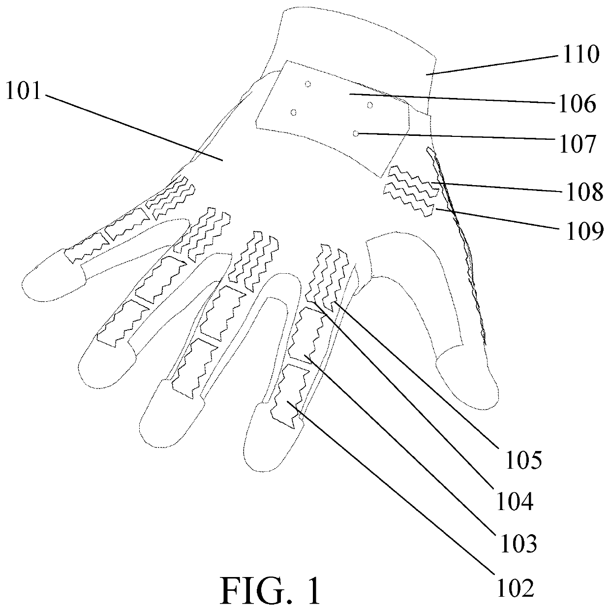
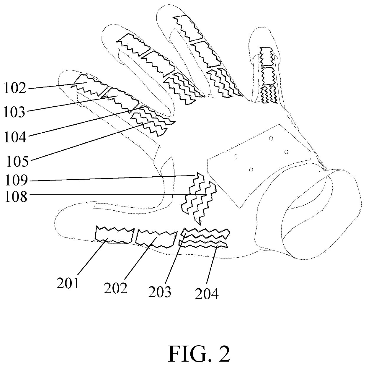
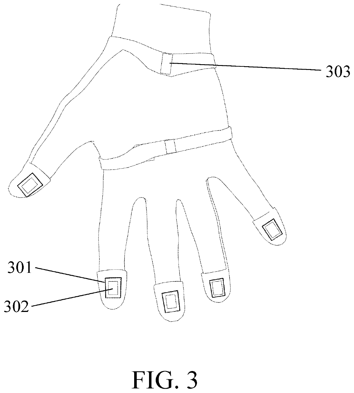
[0014]One embodiment of the device is shown in FIG. 1 (overview), FIG. 2 (thenar view), and FIG. 3 (palmar view). This embodiment of the device is worn on the hand but other embodiments may be worn on other parts of the body. A flexible, elastic substrate 101 is worn on the user's hand 110. Said substrate 102 may be made from an elastomer such as silicone or polyurethane, or a woven elastic textile such as Lycra.

[0015]Conductive loops 102, 103, 104, 105, 108 and 109 are mounted upon, woven into or embedded within said substrate 102. The basic structure for each finger, formed by the set up loops 102, 103, 104, 105, may be taken as being repeated for each digit as shown in the figure. In addition to the same four loops as the other digits, the thumb is also provided with two additional loops 108 and 109.

[0016]In some embodiments of the device the conductive loops 102, 103, 104, 105, 108 and 109 are made of metal wire such as copper which is of a thickness that they can bend repeatedl...


PUM


Abstract

A wearable device comprises a flexible substrate carrying multiple conducting loops which are formed into a zig zag pattern so as to be able to accommodate a stretching of the substrate. The substrate is formed into a glove and the loops positioned such that they are aligned with the anatomical joints. As the anatomical joints move, the loops change shape and accordingly change their inductance—this is measured by the electronics in the glove and used to calculate the joint angles in a processor which transmits the angles to an external computer system. Some of the loops are attached to current drivers in the electronics module, and a magnet positioned close to the loop, providing means for a force to be generated between magnet and loop when the current driver passes current through the loop, thereby providing tactile feedback to the user.

Description

FIELD OF THE INVENTION[0001]The present invention relates to computer human interface devices, and more specifically to interface devices can be worn on and which interface with parts of the human body such as the hand. Such devices are useful in interacting with computer programs, such as interacting three dimensional representations of objects or data, or in the context of virtual reality, and in capturing body motion for later replay.BACKGROUND OF THE INVENTION[0002]Some previous devices have used resistive flex sensors incorporating partially conductive elastomeric materials to measure the flexion of hand joints. These devices have the disadvantage that the value measured depends on the joint angle in a nonlinear way, and also upon previous joint angles, that is to say they display hysteresis. These devices have the further disadvantage that the value measured changes with temperature. These devices have the further disadvantage that they consist of several components—electrodes...

Claims


Application Information

Patent Timeline
Patent Type & Authority Applications(United States)
IPC IPC(8): G06F3/01G01B7/30
CPCG06F3/016G06F3/014G01B7/30G06F1/163G06F3/017G01R27/2611G06F3/0346
Inventor HOGBIN, MATTHEW
Owner PLEXUS IMMERSIVE CORP
Learn More