Laminated glass

Active Publication Date: 2020-05-14
ASAHI GLASS CO LTD
View PDF1 Cites 3 Cited by
  • Summary
  • Abstract
  • Description
  • Claims
  • Application Information

AI Technical Summary

Benefits of technology

The present invention aims to improve the appearance and heat uniformity of an electrically heatable laminated glass. The technique described in the patent text helps to achieve this goal.

Problems solved by technology

Although the above electric heating glass can be applied to side glass for an automobile, the side glass is often not in a simple rectangular or trapezoid shape as compared with the windshield or the like, and it is difficult to uniformly generate heat.
In particular, the side glass that can be lifted and lowered cannot provide a sufficient concealment area through printing, and a bus bar is desired to be arranged alongside the lower side from the viewpoint of appearance and protection of the conductive elements from moisture, which makes the current flow path to be complicated as compared with the windshield.
Therefore, the structure for sealing the metal wiring is difficult to manufacture.
However, the presence of the insulating wiring is not preferable in terms of appearance.

Method used


Image

  • Laminated glass
  • Laminated glass
  • Laminated glass

Examples


first embodiment

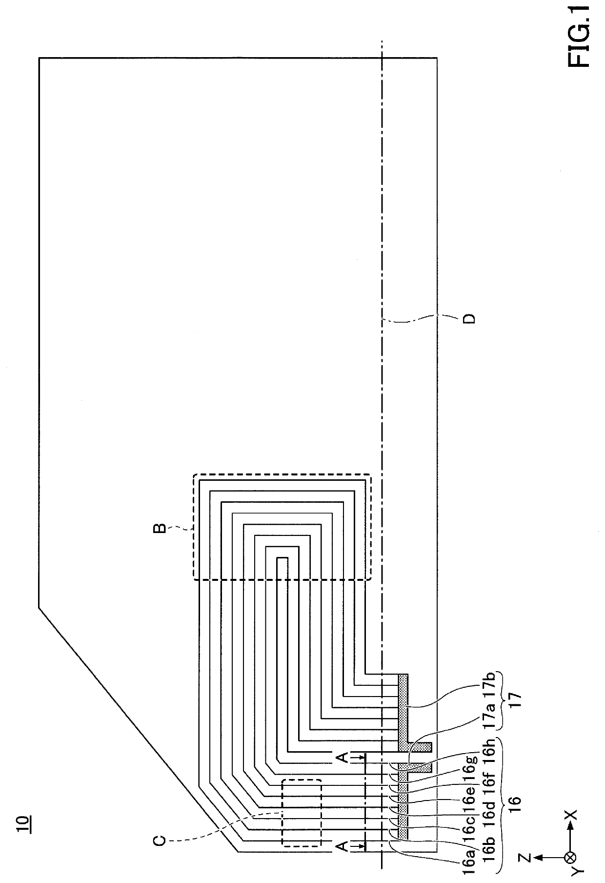
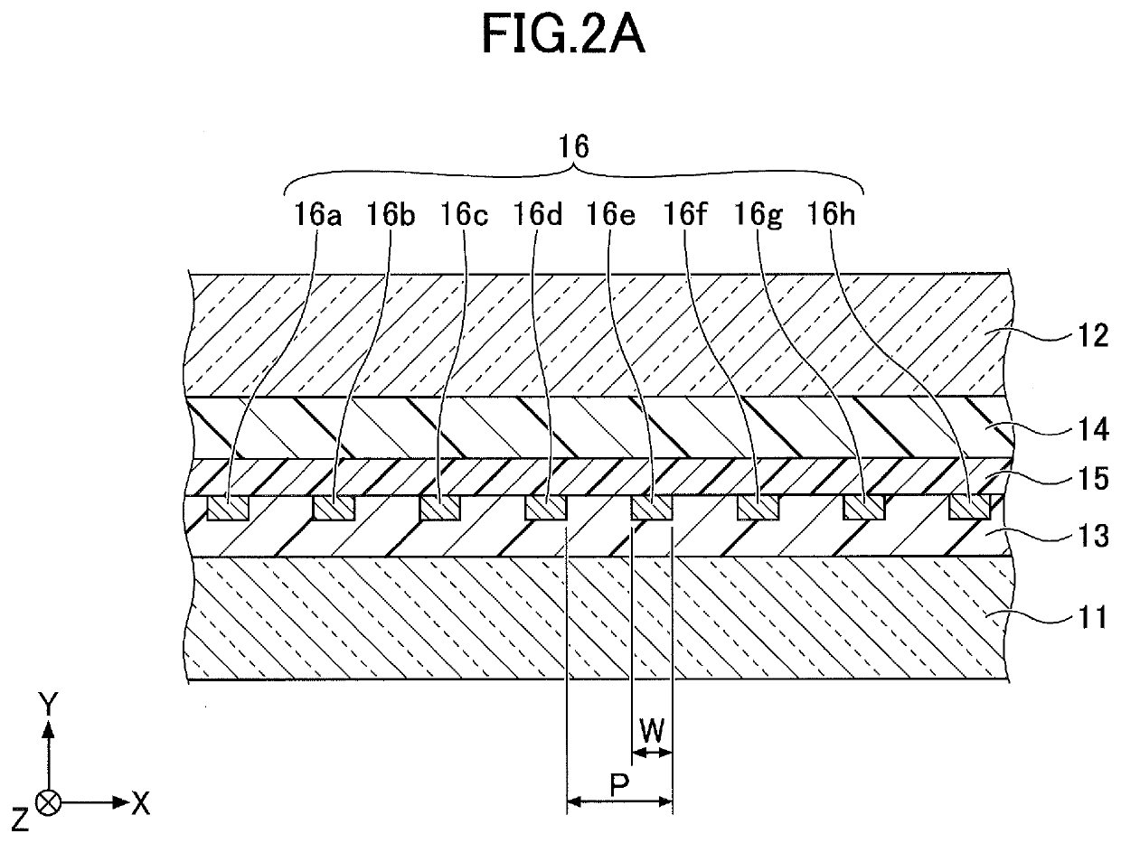
[0026]FIG. 1 is a drawing illustrating a side glass for a vehicle according to the first embodiment. FIG. 2A is a partially enlarged cross-sectional view taken along line A-A of FIG. 1. In FIG. 1, a left-hand side (the base of arrow X) corresponds to the front, and a right-hand side (the tip of arrow X) corresponds to the rear, when side glass 10 is attached to the vehicle. In FIG. 1, the lower side (the base of arrow Z) corresponds to the floor side, and the upper side (the tip of the arrow Z) corresponds to the roof side, when the side glass 10 is attached to the vehicle. In FIG. 1, an area below an alternate long and short dash line D is an area that is hidden behind the vehicle body and cannot be seen from the outside of the vehicle when the side glass 10 is attached to the vehicle.

[0027]As illustrated in FIG. 1 and FIG. 2A, the side glass 10 includes, as main constituent elements, a pair of glass plates 11 and 12, a pair of intermediate adhesive layers 13 and 14, and a base mat...

second embodiment

Modification of Second Embodiment

[0076]The modification of the second embodiment shows an example in which detailed specifications are changed in the second embodiment. In the modification of the second embodiment, the explanations about the same constituent elements as those already described may be omitted.

[0077]FIG. 5 is a drawing illustrating a side glass for a vehicle according to the modification of the second embodiment. The side glass 10B illustrated in FIG. 5 is generally similar to the side glass 10A (see FIG. 4), but the details are different.

[0078]FIG. 6 is an enlarged view illustrating a portion E of FIG. 5. As illustrated in FIG. 6, in the side glass 10B, a pitch P1 between nearest line segments of an innermost conductive thin wire at the turnaround is equal to a pitch P2 of conductive thin wires around the innermost conductive thin wire. In other words, the pitch P1 of the conductive thin wire 16h turned back in the smallest loop is equal to the pitch P2 of conductive...

third embodiment

[0086]The third embodiment is an example for providing a plurality of sets of bus bars. In the third embodiment, the explanations about the same constituent elements as those already described may be omitted.

[0087]FIG. 9 is a drawing illustrating a side glass for a vehicle according to the third embodiment. The side glass 10C illustrated in FIG. 9 is different from the side glass 10A (see FIG. 4) in that the side glass 10C includes two zones (zone Z1 and zone Z2) arranged in parallel in the X direction and configured to be able to heat substantially the entirety of the side glass 10C. In the side glass 10C, the specification of the zone Z1 is the same as that of the side glass 10A, and the explanation thereabout is omitted.

[0088]In the side glass 10C, the zone Z2 is provided with one set of bus bars 27 independent of the bus bars 17 in the zone Z1. In the present embodiment, there are two aggregations of conductive thin wires in which currents flow in the same direction, and there a...


PUM

PropertyMeasurementUnit
Fractionaaaaaaaaaa
Lengthaaaaaaaaaa
Lengthaaaaaaaaaa

Abstract

A laminated glass includes a pair of glass plates facing each other, a pair of intermediate adhesive layers positioned between the pair of glass plates and in contact with the respective glass plates, a wiring positioned between the pair of intermediate adhesive layers, and one set of bus bars connected to the wiring. The wiring includes conductive thin wires arranged in parallel with each other between the bus bars. The bus bars are arranged alongside a same edge of the glass plates. In an area corresponding to at least a part of a principal face of the glass plates, the conductive thin wires are arranged as one aggregation and include at least one turnaround. A resistance value of each of the conductive thin wires is within a range of 10% or less with respect to an average value of resistance values of the conductive thin wires.

Description

CROSS-REFERENCE TO RELATED APPLICATIONS[0001]The present application is a continuation application filed under 35 U.S.C. 111(a) claiming benefit under 35 U.S.C. 120 and 365(c) of PCT International Application No. PCT / JP2018 / 030042 filed on Aug. 10, 2018 and designating the U.S., which claims priority of Japanese Patent Application No. 2017-162339 filed on Aug. 25, 2017. The entire contents of the foregoing applications are incorporated herein by reference.BACKGROUND OF THE INVENTION1. Field of the Invention[0002]The present invention relates to a laminated glass.2. Description of the Related Art[0003]In window glass for vehicles such as automobiles and railways, laminated glass in which electric heating wiring is sandwiched (electric heating glass) for removing frozen moisture attached to the window glass in winter (i.e., de-icing) and clear the fog on the window glass (i.e., defogging) is widely known.[0004]Specific examples of the electric heating glass include a so-called heat wi...

Claims


Application Information

Patent Timeline
IPC IPC(8): H05B3/86H05B3/34B32B17/10
CPCH05B3/86H05B2203/014B32B17/10036H05B3/34H05B2203/002H05B2203/011B32B7/02B32B17/06B60S1/02H05B2203/003H05B2203/004
Inventor GIMA, YUHEIMIYASAKA, SEIICHINAKAMURA, SHIGERU
Owner ASAHI GLASS CO LTD
Why Eureka
Try Eureka