Cabinet structure for storing at least one shoe

a shoe cabinet and shoe technology, applied in the field of shoe cabinets, can solve the problems of reducing the available storage space in the shoe cabinet, trouble for families, and inefficient use of the empty space in the cabinet, and achieve the effect of easy rotation of the fram

Inactive Publication Date: 2020-05-21
PATYA DESIGN LTD
View PDF0 Cites 8 Cited by
  • Summary
  • Abstract
  • Description
  • Claims
  • Application Information

AI Technical Summary

Benefits of technology

[0009]One objective of the present disclosure is to provide a cabinet structure for storing at least one shoe. The cabinet structure includes a body and a sliding frame set. The body includes a cabinet body and at least one door leaf. The cabinet body is provided therein with an accommodating space. The door leaf is movably assembled to a front side of the cabinet body so as to expose the accommodating space when opened and shield the accommodating space when closed. The sliding frame set includes two fixing members, two sliding memb

Problems solved by technology

This shelf arrangement, however, fails to make efficient use of those empty spaces in the cabinet that are adjacent to the toe boxes of the shoes.
The very arrangement also limits the number of shoes that can be placed in the cabinet, so a user having more shoes than can be stored in one shoe cabinet cannot but use more shoe cabinets, which nevertheless causes trouble to families whose living space is at a premium e.g., those living in apartments).
Moreover, people tend to put shoehorns, shoe polish, air fresheners and so on in a shoe cabinet for ease of use, but these additional items are bound to reduce the available storage space in the shoe cabinet.
(1) Generally, a conventional auxiliary hanging member is fixed to a panel of a shoe cabinet by screws, nails, adhesive or the like. While the aforesaid fixing methods are effec

Method used


Image

  • Cabinet structure for storing at least one shoe
  • Cabinet structure for storing at least one shoe
  • Cabinet structure for storing at least one shoe

Examples


Embodiment Construction

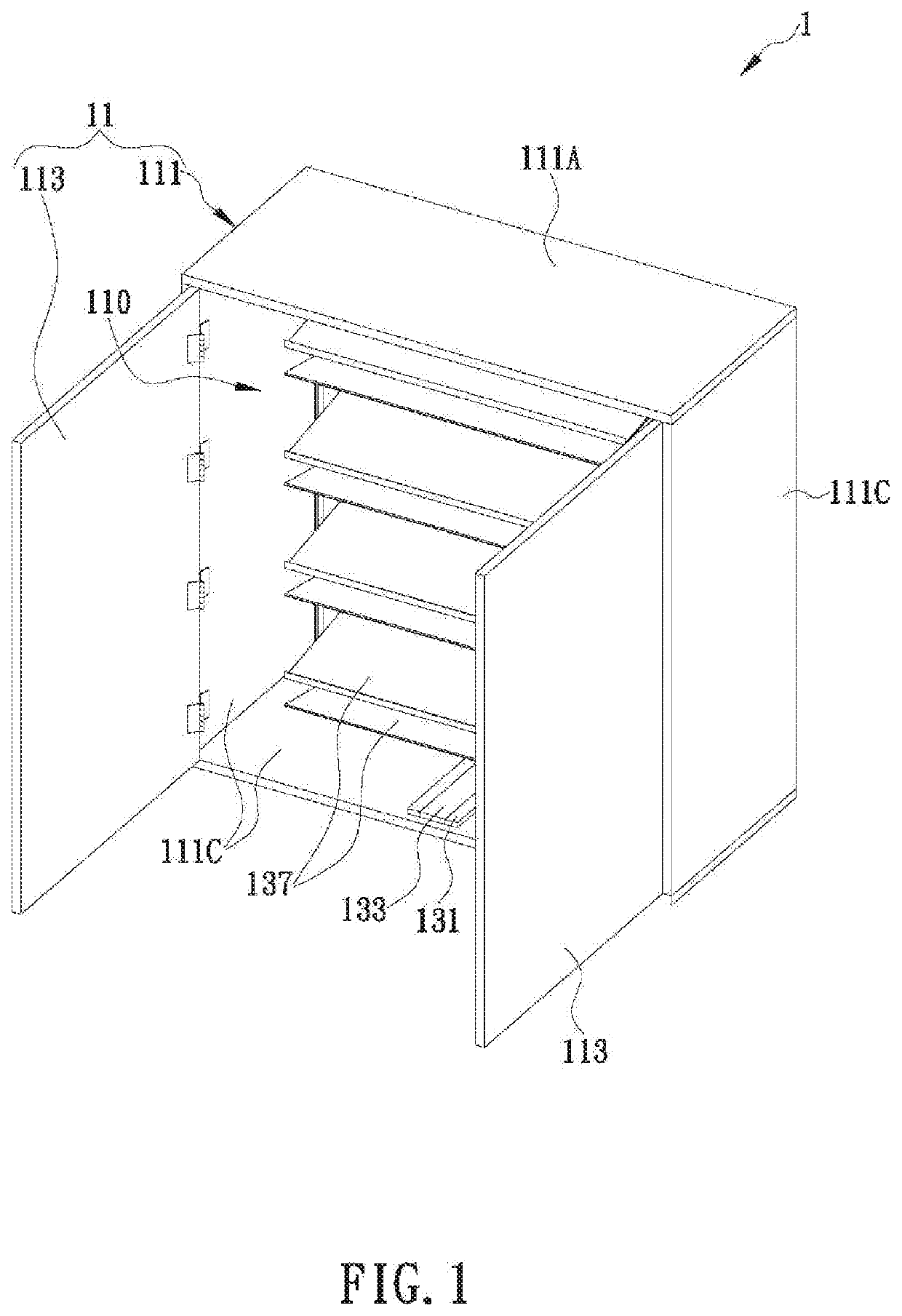
[0023]The present disclosure provides a cabinet structure for storing at least one shoe. In certain embodiments, as shown in FIG. 1, the cabinet structure 1 for storing at least one shoe includes a body 11 and a sliding frame set 13. To facilitate description, the top side of each component described herein is defined as the side facing the top edge of FIG. 1, the bottom side of each component is defined as the side facing the bottom edge of FIG. 1, the front side of each component is defined as the side facing the lower left corner of FIG. 1, and the rear side of each component is defined as the side facing the upper right corner of FIG. 1. The configuration of the cabinet structure 1 is by no means limited to that shown in FIG. 1, and all the components of the cabinet structure 1 may be adjusted in configuration according to product requirements, provided that the cabinet structure 1 has the essential structures and effects disclosed below.

[0024]As shown in FIG. 1, the body 11 inc...


PUM


Abstract

A cabinet structure for storing at least one shoe includes a body and a sliding frame set. The body includes a cabinet body and at least one door leaf. The door leaf can be movably assembled to a front side of the cabinet. The sliding frame set includes two fixing members, two sliding members and a frame. The two fixing members can be fixed respectively to an inner top surface and an inner bottom surface of the cabinet body. The two sliding members can be movably assembled to the fixing members respectively. A plurality of placement plates for placing the at least one shoe are arranged at the frame and pivoted between the two sliding members to facilitate a user to place shoes at two lateral sides of the frame and access shoes placed at each of the lateral sides by rotating the frame.

Description

FIELD[0001]The present disclosure relates to shoe cabinets and more particularly to a cabinet structure configured to store shoes while making efficient use of the space inside the structure.BACKGROUND[0002]With the rise of living standards, it has been very common for one to have many pairs of shoes. On average, therefore, a typical family may have dozens of pairs of shoes, which are usually stored in shoe cabinets located at the front door, or in the entry way, of the family's dwelling.[0003]Generally, a shoe cabinet includes a number of shelves placed in the interior space of the cabinet to divide the space into a plurality of storage areas where a user of the cabinet may put his or her shoes when the shoes are not in use. Such a shoe cabinet not only allows shoes to be neatly arranged on the shelves as opposed to being scattered around or piled up in a disorderly manner, but also protects the shoe surface from contamination by dust, rainwater or other contaminants. Hence, shoe c...

Claims


Application Information

Patent Timeline
IPC IPC(8): A47B61/04A47B46/00A47B49/00
CPCA47B46/00A47B61/04A47B49/004A47B88/42A47F7/08A47B2210/0056A47B2210/0062
Inventor HUANG, SHIH-MING
Owner PATYA DESIGN LTD
Why Eureka
Try Eureka