
Patient table and patient weight measuring system

a patient table and patient technology, applied in the field of weighing patients, can solve the problems of inefficiency of discrete weight-measuring tasks, difficulty in standing on a scale for disabled patients, and difficulty in discrete weight-measuring tasks

Active Publication Date: 2020-05-21
GENERAL ELECTRIC CO
View PDF0 Cites 3 Cited by
  • Summary
  • Abstract
  • Description
  • Claims
  • Application Information

AI Technical Summary

Benefits of technology

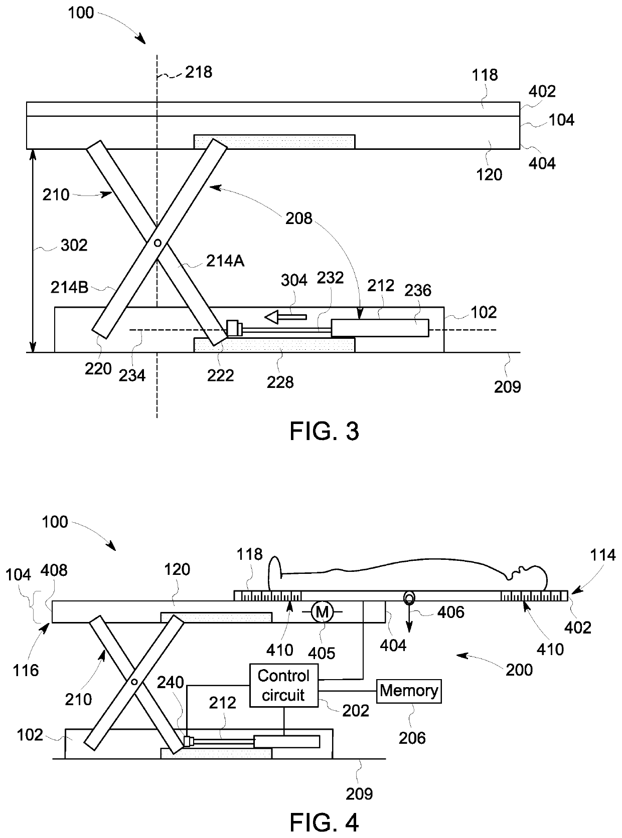
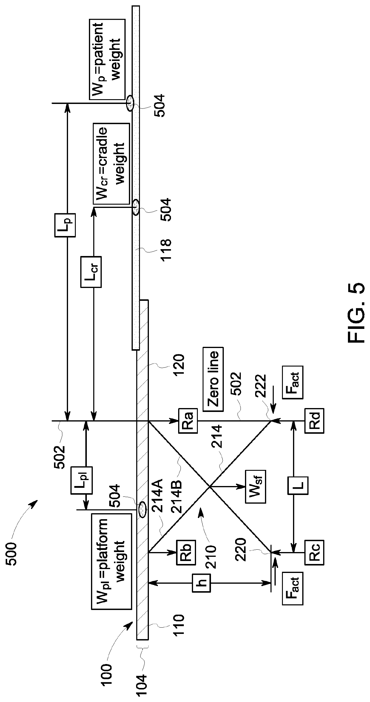
The invention is a patient table with an elevation mechanism, load sensor, and control circuit that can measure the weight of a patient on the table. The elevation mechanism includes a support frame and actuator that can adjust the height of the table top to accommodate patients. The load sensor is connected to the actuator and measures the force applied by the actuator to control the table's height. The control circuit calculates the weight of the patient based on the membrane force measured by the load sensor. The technical effects include improved mobility and accuracy in patient positioning for medical imaging, as well as in other medical procedures where patient weight measurement is important.

Problems solved by technology

The discrete weight-measuring task is generally inefficient because it delays the impending examination of the patient and the examination of other patients scheduled to be examined after the patient.
Furthermore, the weight-measuring task may be difficult and / or embarrassing for some patients.
For example, disabled patients may have difficulty standing on a scale, and overweight patients may experience anxiety as the medical worker views and records the readout of the scale.

Method used


Image

  • Patient table and patient weight measuring system
  • Patient table and patient weight measuring system
  • Patient table and patient weight measuring system

Examples


Embodiment Construction

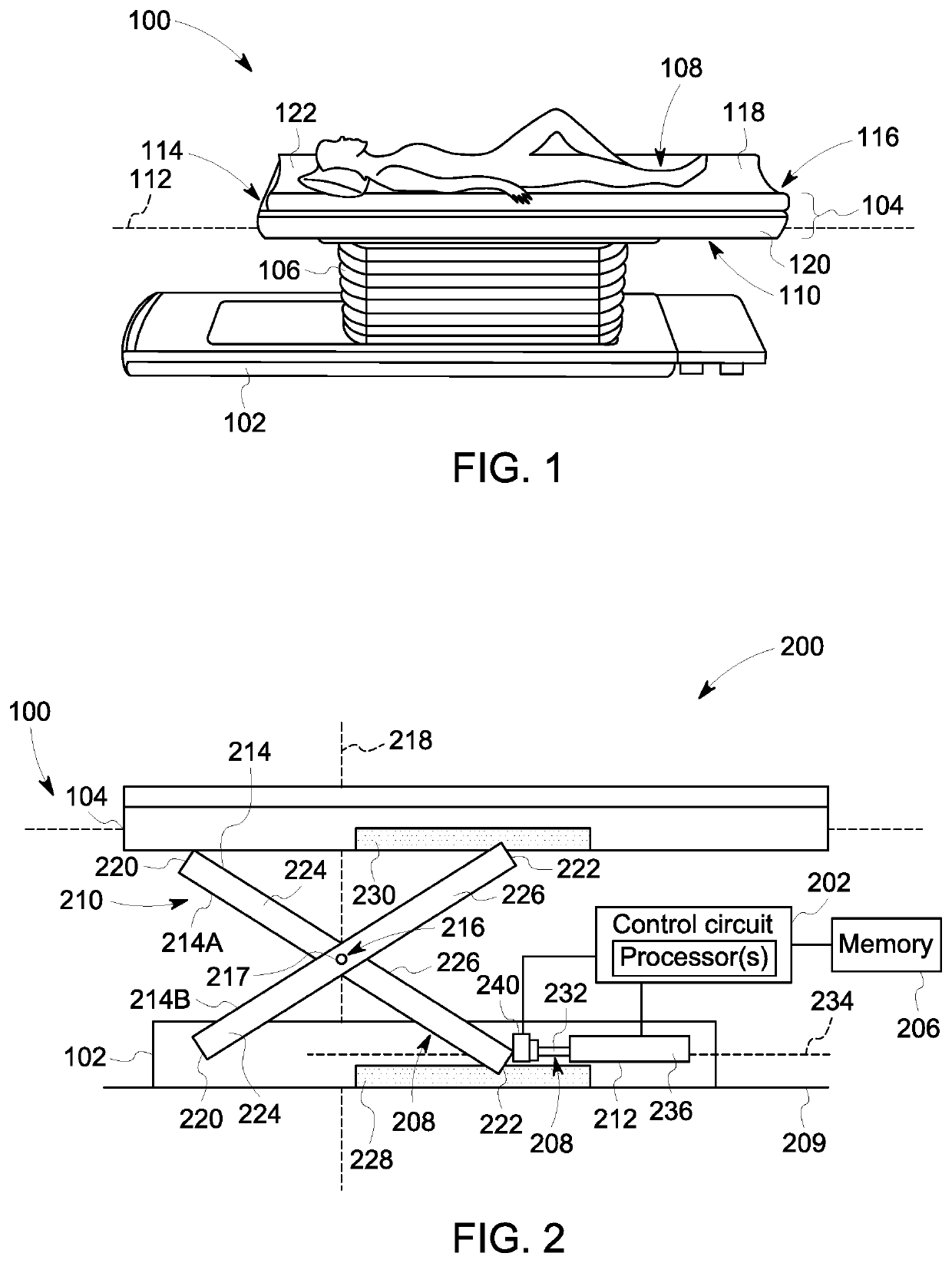
[0017]One or more embodiments of the inventive subject matter described herein provide a patient weight measuring system that is configured to automatically weigh a patient as the patient sits or lies on a patient table. For example, instead of asking the patient to stand on a scale, a medical facility that includes the patient weight measuring system described herein can skip the separate weight-measuring task and bring the patient directly to a medical room that includes the patient table. The patient table may be utilized for medical imaging, such that a region of the patient's body is imaged while the patient is disposed on the patient table. For example, the patient table may be used with various medical imaging modalities, such as a Positron Emission Tomography (PET) imaging system, a Single Photon Emission Computed Tomography (SPECT) imaging system, a Computed Tomography (CT) imaging system, a Magnetic Resonance Imaging (MRI) imaging system, an X-Ray imaging system, an ultras...


PUM


Abstract

Patient weight measuring system includes a patient table and a control circuit. The patient table includes a tabletop that receives a patient thereon, an elevation mechanism, and a load sensor. The elevation mechanism adjusts a height of the tabletop relative to a floor. The elevation mechanism includes a support frame and an actuator. The support frame includes multiple pivotable frame members mechanically connected to the tabletop. The actuator is configured to exert an actuator force on at least one of the frame members to control the height of the tabletop. The load sensor is operably connected to the actuator and configured to measure the actuator force. The control circuit is communicatively connected to the load sensor, and is configured to calculate a weight of the patient disposed on the tabletop based on the actuator force measured by the load sensor.

Description

FIELD[0001]The subject matter disclosed herein relates generally to weighing patients in a medical environment.BACKGROUND[0002]Measuring and recording a patient's weight is a standard practice in medical facilities, such as clinics, hospitals, doctor's offices, physical therapy centers, and the like. The patient weight is typically acquired during a discrete weight-measuring task in which the patient is asked to stand on a scale and a medical worker records the measured weight in a file. The weight-measuring task may be performed prior to the patient being admitted to an examination room to consult with a doctor or other medical professional and / or to perform medical imaging, surgery, or another medical task. The discrete weight-measuring task is generally inefficient because it delays the impending examination of the patient and the examination of other patients scheduled to be examined after the patient. Furthermore, the weight-measuring task may be difficult and / or embarrassing f...

Claims


Application Information

Patent Timeline
Patent Type & Authority Applications(United States)
IPC IPC(8): A61G13/06A61B6/04A61G13/00
CPCA61G2203/32A61G13/0018A61G13/126A61B6/0442A61G13/06A61G2203/44
Inventor LUYBANSKY, MICHAEL
Owner GENERAL ELECTRIC CO
Learn More