
Gas downcomer pipe, installation member and desulfurization apparatus

Active Publication Date: 2020-05-21
CHIYODA CORP
View PDF0 Cites 0 Cited by
  • Summary
  • Abstract
  • Description
  • Claims
  • Application Information

AI Technical Summary

Benefits of technology

The present invention provides a gas downcomer pipe, an installation member, and a desulfurization apparatus that can prevent the accumulation of deposits and simplify the installation process in a partition wall.

Problems solved by technology

However, when the through holes have to be replaced at a predetermined frequency because of degradation or damage, the replacement operation requires a vast period of time and can by turn give rise to damages in the tank main body including the partition wall.

Method used


Image

  • Gas downcomer pipe, installation member and desulfurization apparatus
  • Gas downcomer pipe, installation member and desulfurization apparatus
  • Gas downcomer pipe, installation member and desulfurization apparatus

Examples


modified example

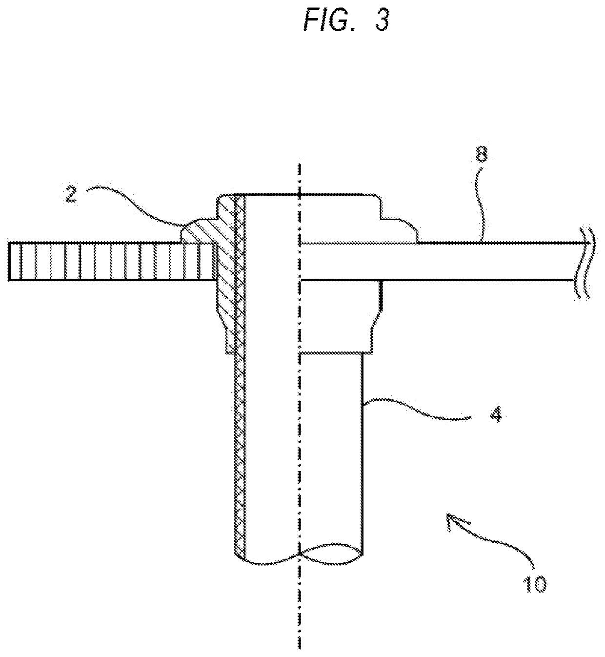
[0057]Now, a modified example of the gas downcomer pipe in this mode of carrying out the present invention will be described by referring to FIG. 3 and FIG. 4.

[0058]FIG. 3 is a schematic cross-sectional view of a modified example of the gas downcomer pipe, which is in a mode of carrying out the present invention and its periphery, showing the configuration thereof and FIG. 4 is an enlarged schematic partial view of the installation member in FIG. 3.

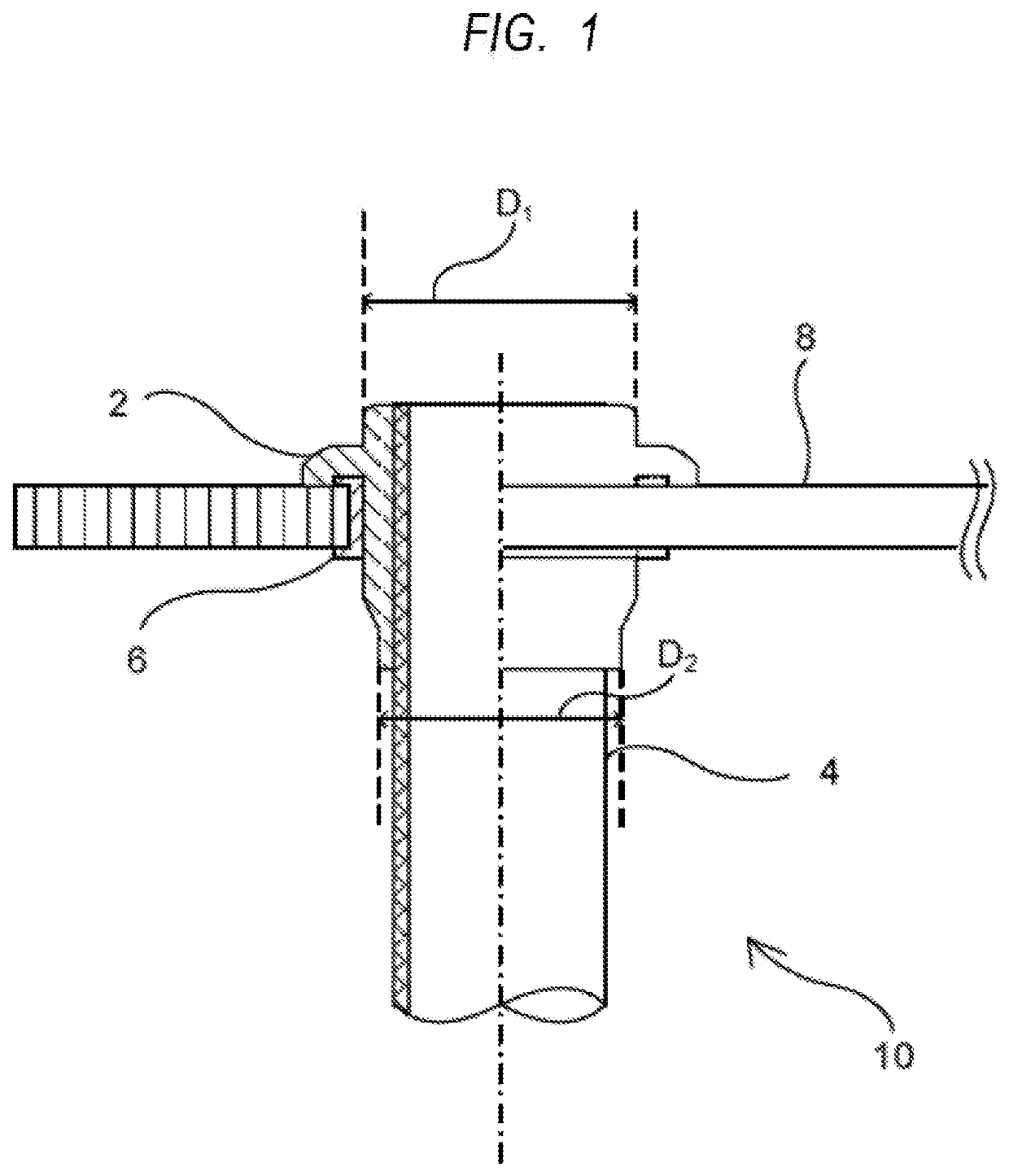
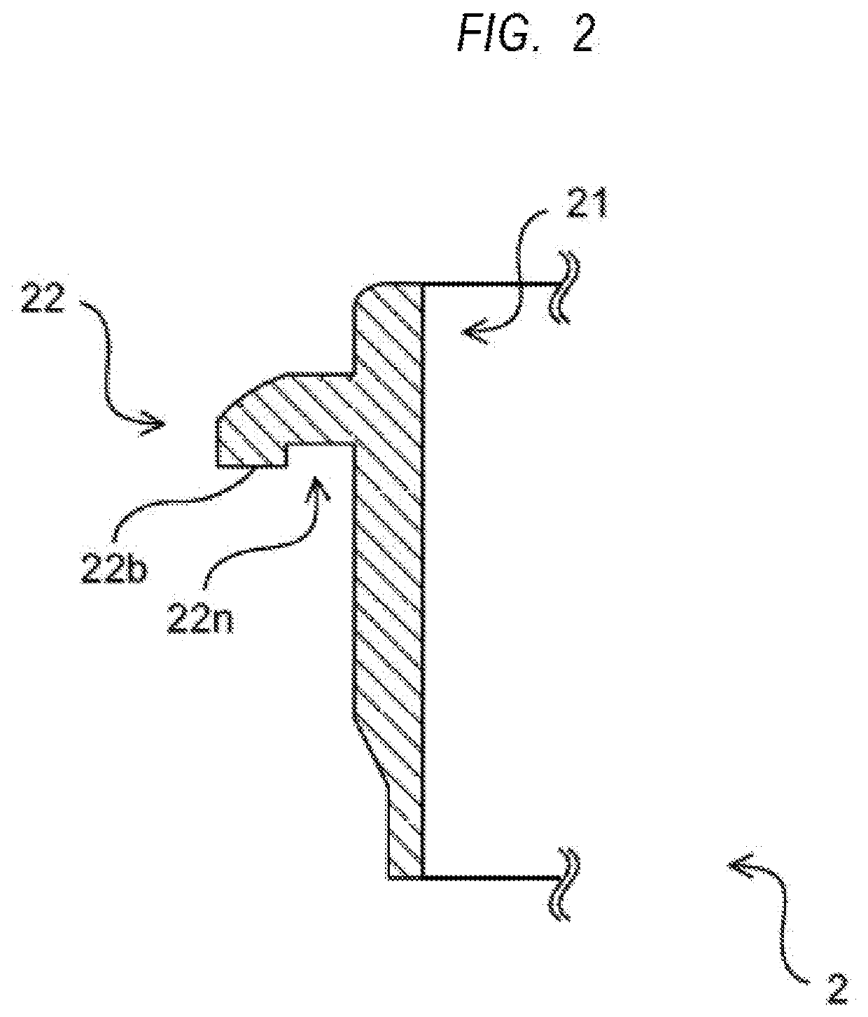
[0059]Note that only the differences from the configuration shown in FIG. 1 and FIG. 2 will be described below and description of the parts of the configuration that are the same as those of FIG. 1 and FIG. 2 will be omitted.

[0060]With the modified example shown in FIG. 3 and FIG. 4, the bottom surface 22b of the protruding part 22 shows a flat profile and is not provided with the cutout section 22n shown in FIG. 1 and FIG. 2. Additionally, no elastic member 6 shown in FIG. 1 is provided.

[0061]Therefore, the outer wall of the gas downcome...


PUM

PropertyMeasurementUnit
Diameteraaaaaaaaaa
Elasticityaaaaaaaaaa

Abstract

There are provided a downcomer pipe that can achieve suppression of accumulation of deposits in use and simplification of operation when being installed into a partition wall, an installation member and a desulfurization apparatus. The downcomer pipe comprises a pipe-shaped member and an installation member for installing the pipe-shaped member into the partition wall. The installation member includes a pipe-shaped part whose inner wall is to be brought into contact with the outer wall of the pipe-shaped member and a protruding part arranged on the outer wall of the pipe-shaped part, the pipe-shaped part and the protruding part constituting an integrated member.

Description

TECHNICAL FIELD[0001]The present invention relates to a gas downcomer pipe and an installation member used in a desulfurization apparatus, and a desulfurization apparatus.BACKGROUND ART[0002]There are known conventional structures in various plants such as those of gas absorption equipment that are made to allow gas or liquid to flow among a plurality of spaces, which are formed by dividing a tank by means of a partition wall, by way of through pipes by arranging the through pipes to run through the partition wall. Then, such through pipes may be connected (fastened) to the partition wall by means of welding or the like. However, when the through holes have to be replaced at a predetermined frequency because of degradation or damage, the replacement operation requires a vast period of time and can by turn give rise to damages in the tank main body including the partition wall.[0003]For this reason, Patent Literature 1 discloses a multi-pipe type gas-liquid contact device that compri...

Claims


Application Information

Patent Timeline
IPC IPC(8): B01D53/18B01D53/78B01D53/50
CPCB01D53/78B01D53/504B01D53/18B01D2257/404B01D2258/0283B01D2252/103B01D2257/302F16L5/00F16L5/02
Inventor KUMAGAI, KAZUYAKUROSAKI, NAOBUMI
Owner CHIYODA CORP
Learn More