
Trim balance weight installation tool and method for installing a trim balance weight in a rotor

a technology of trim balance weight and installation tool, which is applied in the direction of machines/engines, manufacturing tools, mechanical equipment, etc., can solve the problems of foreign object damage, tool pinching or damaging the airfoil in the process,

Inactive Publication Date: 2020-05-21
MTU AERO ENGINES GMBH
View PDF3 Cites 2 Cited by
  • Summary
  • Abstract
  • Description
  • Claims
  • Application Information

AI Technical Summary

Benefits of technology

The present invention is a tool for bending that achieves better results compared to previous claw mechanisms. Additionally, the tool is made entirely of plastic, which reduces the risk of damage to the leading edge and prevents foreign objects from entering the turbine. The plastic tool is also easier to install and use.

Problems solved by technology

These tools have struggled to secure the trim balance, which can result in liberated balance weights during operation.
These tools also risk pinching or damaging the airfoil in the process, for example due to the hook required to interact with the leading edge.
Moreover, the tools have generally been made of metal, so if parts of the tool break off or the tool is left whole in the engine, foreign object damage can occur.

Method used


Image

  • Trim balance weight installation tool and method for installing a trim balance weight in a rotor
  • Trim balance weight installation tool and method for installing a trim balance weight in a rotor
  • Trim balance weight installation tool and method for installing a trim balance weight in a rotor

Examples


first embodiment

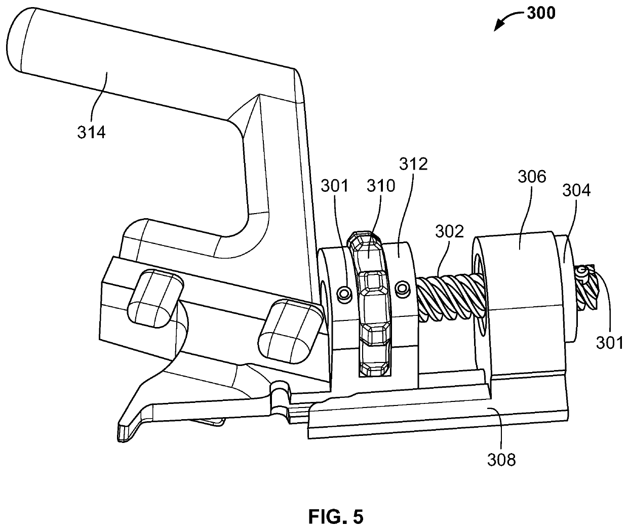
[0032]FIG. 5 shows an installation tool 300 of the present invention in a retracted position. Tool 300 in this preferred non-limiting embodiment is manufactured completely by 3-D printing a plastic such as an ABS or PETG plastic as will be described. Should a part or the entirety of the tool 300 be left in the engine, the plastic will burn up, minimizing foreign object damage.

[0033]Tool 300 has a tool body 312, a handle 314 fixedly connected to the tool body 312, for example via a friction fit, and a linear actuator 308. Linear actuator 308 has an integral thread support 306, which fixedly supports an internally-threaded thread nut 304. Thread nut 304 can fit into a hole on the integral thread support. A radially-extending flange on the thread nut 304 can rest against a side surface of the thread support 306.

[0034]As shown in FIG. 9, tool body 312 can have two parallel spaced-apart thumb-screw supports, as well as a support 313 with a support surface 317 extending perpendicularly wi...

embodiment 400

[0041]FIGS. 15 and 16 show schematic isometric views of a second installation tool embodiment 400 with a thumb-activated linear actuator 408. A handle 414 of a tool body with a support 413 can be 3-D printed out of plastic in one piece. Linear actuator 408 can be a thumb pusher, retraction aided by 3-D printed elastomeric tension spring between thumb pusher 408 and the tool body. Support 413 thus can interact as support 313 above during installation, and linear actuator 408 can move tab 204 into position 204′ via thumb force and retract via combined thumb and spring force.

[0042]A worm and worm screw interaction could also be used, for example with the thumb moving the worm screw to activate a linear motion. The handle 314 can be replaced with a long actuator pole and the thumb screw 310 with a worm gear. Access thus can be extended beyond tailcone reach.


PUM


Abstract

An installation tool for an airfoil trim balance weight includes a tool body having a support for supporting the tool body with respect to the trim balance weight. A linear actuator is provided for contacting a tab of the trim balance weight, the linear actuator for moving linearly with respect to the tool body in a linear motion toward the support to permit the tab to bend. A method for installation, a gas turbine engine and a method for manufacturing also are provided.

Description

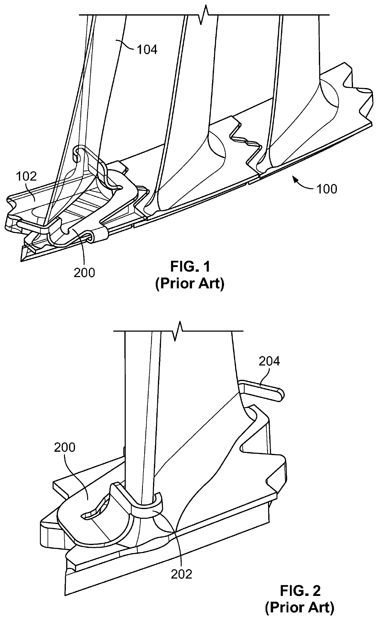
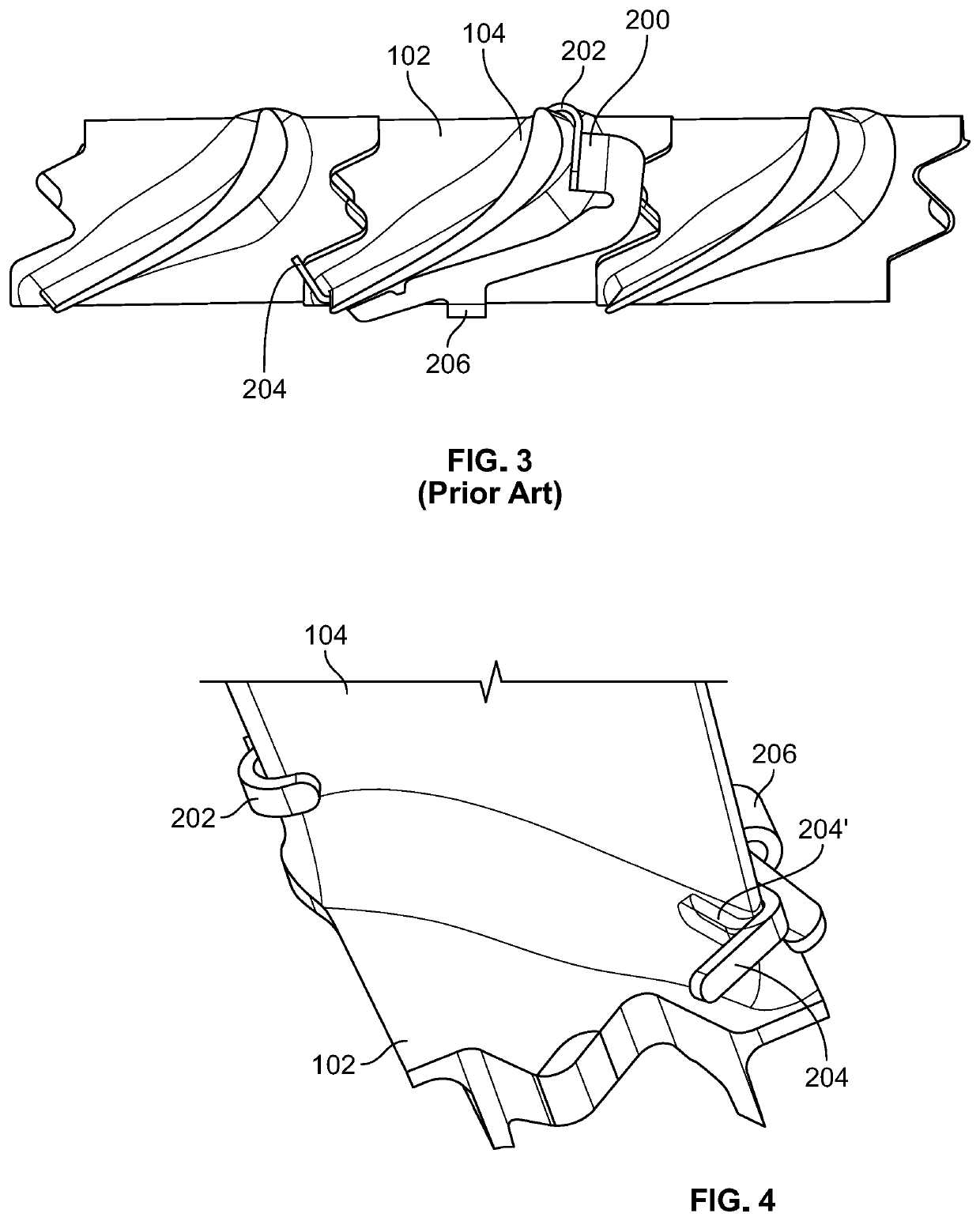
[0001]The present invention relates generally to gas turbine engines, such as aircraft engines, and more particularly to methods and devices for installing trim weights on airfoils of gas turbine engines.BACKGROUND OF THE INVENTION[0002]FIG. 1 shows an aircraft gas turbine engine 100 with a rotor of a low pressure turbine having a plurality of airfoils 104 and radially outer interlocking platforms 102. To balance such rotors it is known to place trim balance weights such as trim balance weight 200 at the end of the airfoil.[0003]FIGS. 2 and 3 show such a trim balance weight 200 attached to the airfoil 104 and platform 102 by being placed between a throat opening between two airfoils 104. Trim balance weight 200 can be made of metal and has a pre-formed tab 202 extending over the leading edge of airfoil 104 and a pre-formed tab 206 extending over an edge of the platform 102. Prior to a final installation step, a further tab 204 extends outwardly from the trailing edge of airfoil 104 ...

Claims


Application Information

Patent Timeline
IPC IPC(8): B25B27/14F01D5/16F01D25/28
CPCF05D2220/323F01D25/28F05D2260/96F01D5/16F05D2230/60B25B27/14F05D2240/30B25B27/0078B25B27/02F01D5/027Y02T50/60
Inventor MATTIA, STEPHENWILBER, JOHN
Owner MTU AERO ENGINES GMBH
Learn More