
End Fitting for a Composite Pipe

Active Publication Date: 2020-05-21
MAGMA GLOBAL
View PDF0 Cites 0 Cited by
  • Summary
  • Abstract
  • Description
  • Claims
  • Application Information

AI Technical Summary

Benefits of technology

The invention provides an apparatus for terminating a composite pipe, which includes a pipe, a connector, and an annular transition element. The apparatus also includes compression means for compressing the extension piece of the liner layer into sealing engagement with the exterior surface of the annular transition element. The invention provides a reliable and effective way to connect composite pipes and ensure a secure and fluid-tight seal at the termination point.

Problems solved by technology

If a composite pipe is used as a subsea flowline, then a contrary challenge may occur, in that the pipe's low specific gravity may allow it to become buoyant and not remain on the sea floor.
Similarly, a composite riser may be unstable when subjected to sea currents and may sway significantly if its specific gravity is too low.
A further obstacle to the introduction of such composite pipes has been the ability to reliably terminate such pipes and to reliably connect them to non-composite piping and apparatus at both subsea and surface interfaces.
The different structural properties of the two materials on the one hand and the differences in thermal expansion on the other, may make it challenging to effect both a reliable structural and sealing connection.

Method used


Image

  • End Fitting for a Composite Pipe
  • End Fitting for a Composite Pipe

Examples


Embodiment Construction

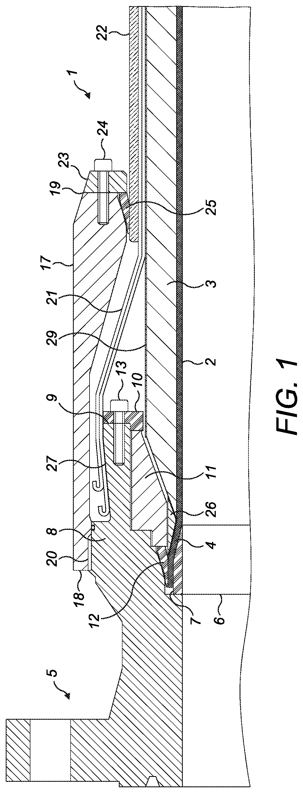
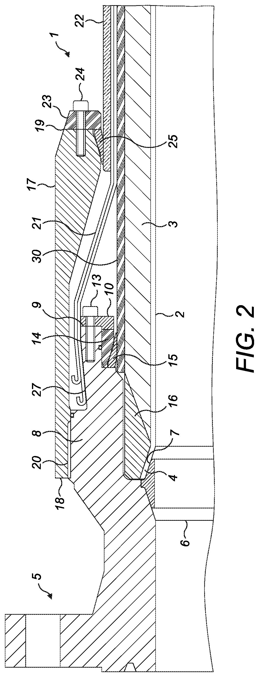
[0038]FIGS. 1 and 2 disclose a first embodiment and a second embodiment respectively of an apparatus for terminating a composite pipe according to the invention.

[0039]Both embodiments illustrate an apparatus comprising a pipe (1) having a liner layer (2) made of PEEK surrounded by a composite layer (3). The composite layer is made of composite material comprising continuous, wound carbon fibres embedded in a PEEK matrix. The pipe is armoured with two layers of spirally wound armouring wires (21) which are enclosed within outer sheath (22) made of extruded polyethylene or extruded polypropylene configured which is present to protect the armouring from the external environment.

[0040]In the embodiments shown in the figures, the composite layer has been chamfered from towards the liner layer at the pipe end and the liner layer (2) includes an extension piece (4) which extends axially beyond the composite layer (3). A connector (5) is provided, made of steel, which, in both cases compris...


PUM

PropertyMeasurementUnit
Thermoplasticityaaaaaaaaaa

Abstract

An apparatus for terminating a composite pipe has a pipe having a liner layer surrounded by a composite layer and a pipe end. The liner layer has an extension piece which extends axially beyond the composite layer at the pipe end; a connector; an annular transition element located between the pipe end and the connector, the annular transition element having an exterior surface; and compression means.

Description

FIELD OF THE INVENTION[0001]The invention relates to an end fitting for a composite pipe of the type used in the oil and gas industry to extract fluid hydrocarbons from subterranean and sub-sea locations. Such pipes and such end fittings are required to operate in hostile environments which may include one or more of high temperature, high pressure, high salinity and high acidity conditions.DESCRIPTION OF THE RELATED ART[0002]Subsea oil and gas drilling and development employs pipes to transport liquid and / or gaseous hydrocarbons from the seabed to the sea surface and to transport injection fluids from the surface to the seabed. These pipes were typically made from steel or from unbonded layers of materials, such as one or more layer(s) of steel wires combined with a plastic liner, which together form a flexible, unbonded steel pipe. Such unbonded, flexible pipes are covered by American Petroleum Institute standard API 17J.[0003]Over time, the subsea depths at which hydrocarbons are...

Claims


Application Information

Patent Timeline
IPC IPC(8): F16L11/08F16L23/024F16L33/01F16L47/14E21B17/08
CPCF16L47/14E21B17/085F16L23/024F16L33/01F16L11/082E21B17/04
Inventor CHARLESWORTH, DAVIDRAMSEY, LUKE
Owner MAGMA GLOBAL
Learn More