Transport device in the form of a long-stator linear motor

Inactive Publication Date: 2020-05-28
B&R IND AUTOMATION GMBH
View PDF0 Cites 1 Cited by
  • Summary
  • Abstract
  • Description
  • Claims
  • Application Information

AI Technical Summary

Benefits of technology

The invention is a transport device in the form of a long-stator linear motor that allows for flexible operation. The problem solved by the invention is the use of multiple transport units with different maximum achievable speeds on the transport path without changing the power electronics units' energy boundary conditions. This is achieved by adjusting the pole pitch of the magnetic poles of each transport unit, which reduces the self-induction voltage at the drive coils and increases the maximum achievable speed. Additionally, a field-weakening mode can be utilized to further increase the maximum speed level.

Problems solved by technology

With the high number of drive coils and power electronics units of a long-stator linear motor, this is of course associated with high complexity and costs, and therefore is generally undesirable.
The disadvantage here is both that the transport units require a power supply for the drive coils and that different sizes of drive coils are necessary for the different transport units, which is very expensive.

Method used


Image

  • Transport device in the form of a long-stator linear motor
  • Transport device in the form of a long-stator linear motor
  • Transport device in the form of a long-stator linear motor

Examples


Embodiment Construction

[0030]The particulars shown herein are by way of example and for purposes of illustrative discussion of the embodiments of the present invention only and are presented in the cause of providing what is believed to be the most useful and readily understood description of the principles and conceptual aspects of the present invention. In this regard, no attempt is made to show structural details of the present invention in more detail than is necessary for the fundamental understanding of the present invention, the description taken with the drawings making apparent to those skilled in the art how the several forms of the present invention may be embodied in practice.

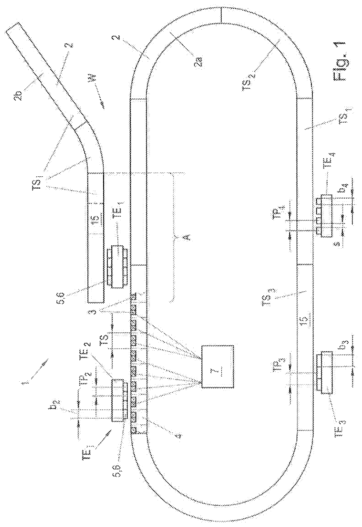
[0031]FIG. 1 shows a transport device 1 according to the invention in the form of a long-stator linear motor. The transport device has, in a known manner, a transport path 2 along which a plurality of transport units TEi can be moved (the index i represents the relevant transport unit TE1-TEi). The transport path 2 forms ...


PUM


Abstract

In order to specify a transport device in the form of a long-stator linear motor, which includes a transport path along which at least two transport units can be moved in the longitudinal direction, and which allows for more flexible operation, the magnetic poles of the at least two transport units have a different pole pitch.

Description

CROSS-REFERENCE TO RELATED APPLICATIONS[0001]The present application claims priority under 35 U.S.C. § 119(a) of Europe Patent Application No. 18 20 8683.5 filed Nov. 27, 2018, the disclosure of which is expressly incorporated by reference herein in its entirety.BACKGROUND1. Field of the Invention[0002]The invention relates to a transport device in the form of a long-stator linear motor, comprising a transport path along which at least two transport units can be moved in the longitudinal direction, a plurality of drive coils being arranged one behind the other in the longitudinal direction on the transport path and a plurality of magnetic poles being arranged one behind the other in the longitudinal direction on the transport units at a specific pole pitch in each case, which interact electromagnetically with the drive coils to move the transport units, each magnetic pole comprising at least one permanent magnet. Furthermore, the invention relates to a transport unit for a transport...

Claims


Application Information

Patent Timeline
IPC IPC(8): H02K41/03B65G23/23
CPCB65G23/23H02K41/031B60L13/03B65G54/02H02K15/0006H02K15/03B65G2812/99
Inventor WEBER, ANDREAS
Owner B&R IND AUTOMATION GMBH
Why Eureka
Try Eureka