
Propulsion system for an aerial vehicle

a propulsion system and aerial vehicle technology, applied in the direction of aircraft convertible vehicles, vertical landing/take-off aircraft, transportation and packaging, etc., can solve the problems of poor performance, inconvenient operation, and inability to move efficiently on the ground, so as to reduce the noise of the propulsion system

Active Publication Date: 2020-06-04
NEFF WILLIAM J
View PDF5 Cites 15 Cited by
  • Summary
  • Abstract
  • Description
  • Claims
  • Application Information

AI Technical Summary

Benefits of technology

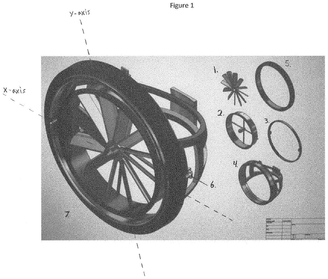
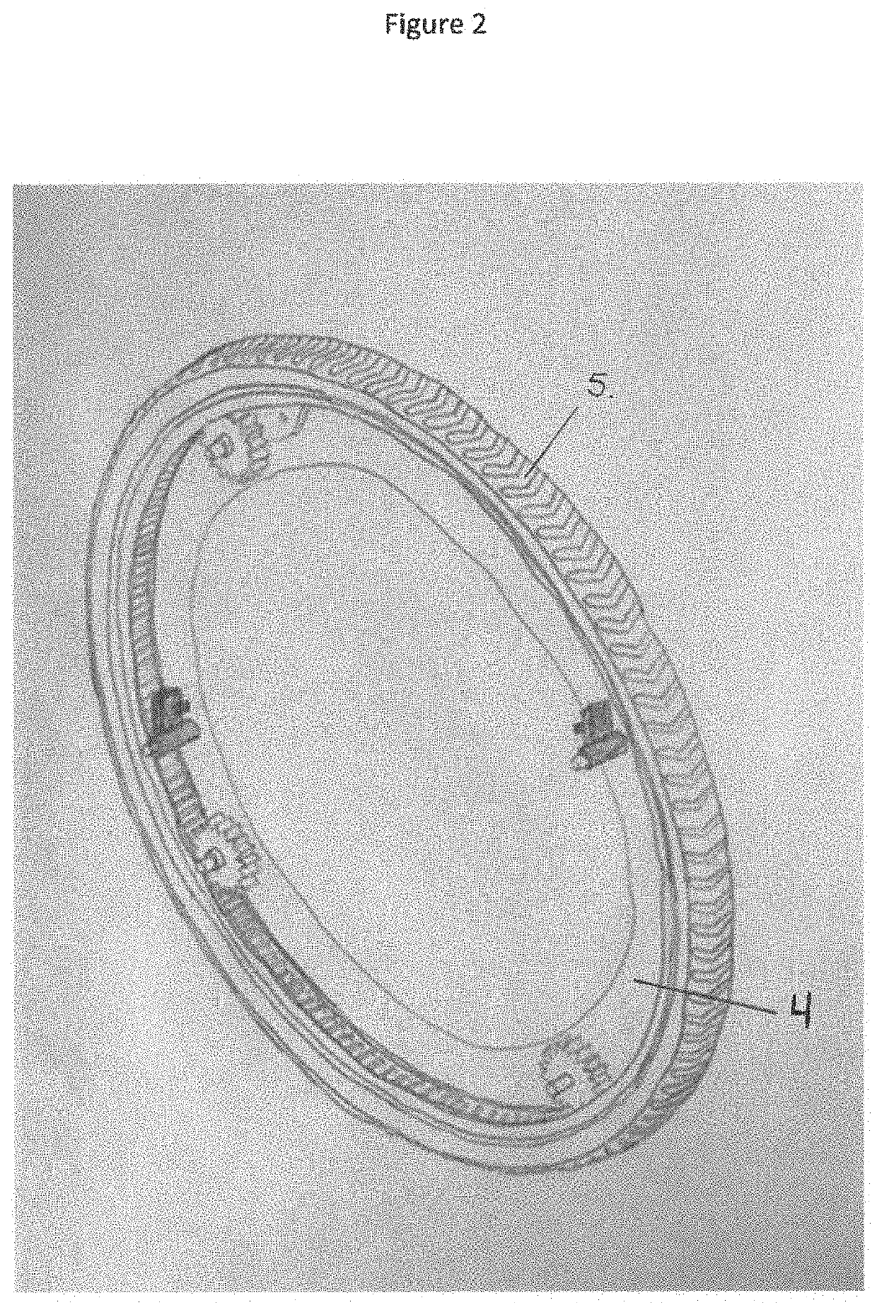
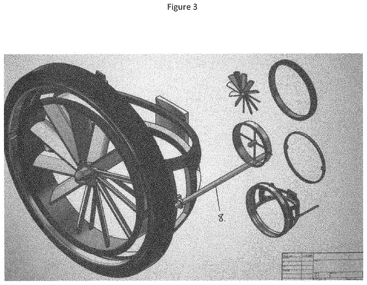
The invention ensures a compact arrangement of a ducted fan or shrouded propeller drive system and the ground-engagement part drive system. This arrangement protects the fan or propeller blades from external objects and reduces noise from the propulsion system.

Problems solved by technology

These approaches have good capabilities in the air, but are not suited for efficient movement on the ground, especially on rough terrain.
However, these vehicles generally do not perform well on the ground and in the air.

Method used


Image

  • Propulsion system for an aerial vehicle
  • Propulsion system for an aerial vehicle
  • Propulsion system for an aerial vehicle

Examples


Embodiment Construction

[0021]Aside from the preferred embodiment or embodiments disclosed below, this invention is capable of other embodiments and of being practiced or being carried out in various ways. Thus, it is to be understood that the invention is not limited in its application to the details of construction and the arrangements of components set forth in the following description or illustrated in the drawings. If only one embodiment is described herein, any claims herein are not to be limited to that embodiment. Moreover, any such claims are not to be read restrictively unless there is clear and convincing evidence manifesting a certain exclusion, restriction, or disclaimer.

[0022]Although specific features of the invention are shown in some drawings and not in others, this is for convenience only as each feature may be combined with any or ail of the other features in accordance with the invention. The words “including”, “comprising”, “having”, and “with” as used herein are to be interpreted bro...


PUM


Abstract

A propulsion system for an aerial vehicle or toy aerial vehicle is disclosed. The system comprises a ducted fan or shrouded propeller drive system for driving the vehicle along ground, the ducted fan or shrouded propeller drive system operating in a plane and having a peripheral ground-engagement part or hubless wheel. The system further comprises a ducted fan or shrouded propeller comprising one or more blades rotatable about a ducted fan or shrouded propeller axis for producing thrust, wherein the ducted fan or shrouded propeller is mounted as such that it may tilt or rotate so that during ground travel it may be in the same plane as the hubless wheel and during operation of the ducted fan or shrouded propeller for flight the blades pass through the plane and inside the hubless wheel. In this way, the ducted fan or shrouded propeller blades of the drive system are protected from blade strikes on obstacles and personnel operating around the ducted fan or shrouded propeller drive system are protected from harm from exposed rotors or blades with no duct or shroud surrounding them.

Description

FIELD OF THE INVENTION[0001]This disclosure relates to a propulsion system for an aerial vehicle, manned or unmanned, which have the capability of traveling on the ground or in the air,BACKGROUND OF THE INVENTION[0002]Currently, the principal approaches for practical vertical-takeoff-and-landing (VTOL) flight vehicles can be grouped into three broad categories: high-speed vehicles using jet thrust or variations of jet thrust and highly loaded lifting fans (e.g., the Harrier and the JSF / F-35B); medium-speed vehicles with rotors (e.g., helicopters and tilt-rotors); and low-speed lifting fan or ducted fan vehicles with more than one lifting fan (such as a flying platform like the Piasecki Flying Jeep). These approaches have good capabilities in the air, but are not suited for efficient movement on the ground, especially on rough terrain.[0003]In many designs, the propulsion system is used to provide both vertical forces for hover and horizontal forces for forward flight. This can be do...

Claims


Application Information

Patent Timeline
IPC IPC(8): B64C29/00B64C37/00B60F5/02B64C27/08B64C25/36B64C25/66
CPCB64C25/66B64C29/0033B64C25/36B60F5/02B64C27/08B64C37/00B64C25/32B64U50/19B64U50/14
Inventor NEFF, WILLIAM J.
Owner NEFF WILLIAM J
Learn More