
Object pose tracking method and apparatus

a tracking method and object technology, applied in the field of robot technology, can solve the problems of prone to lose the target to be tracked, poor robustness of the tracking system, and more difficult to perform the pose tracking on the obj

Active Publication Date: 2020-06-11
UBTECH ROBOTICS CORP LTD
View PDF0 Cites 3 Cited by
  • Summary
  • Abstract
  • Description
  • Claims
  • Application Information

AI Technical Summary

Benefits of technology

This patent describes an object pose tracking method that selects a few 3D models for an object based on its contour and range of viewing angles. By calculating the change in the object's pose and quickly selecting the most relevant 3D model, the method improves accuracy while reducing computational complexity. This can be applied to an object pose tracking apparatus or a computer readable storage medium.

Problems solved by technology

For an object with higher complexity such as an object having multiple sub-parts, or an object having multiple parts can be moved around a main body by rotating or shifting such as an object having tracks or a shovel, it will be more difficult to perform pose tracking on the object.
However, in the case that the speed of the object is increased, or there are many similar straight line features on the object, it is easy to cause the poor robustness of the tracking system and it is liable to lose the target to be tracked.
In addition, if too many features are adopted, the calculation time will be greatly increased, which affects the execution time and the tracking cannot be performed in real time.

Method used


Image

  • Object pose tracking method and apparatus
  • Object pose tracking method and apparatus
  • Object pose tracking method and apparatus

Examples


Embodiment Construction

[0011]In the following descriptions, for purposes of explanation instead of limitation, specific details such as particular system architecture and technique are set forth in order to provide a thorough understanding of embodiments of the present disclosure. However, it will be apparent to those skilled in the art that the present disclosure may be implemented in other embodiments that are less specific of these details. In other instances, detailed descriptions of well-known systems, devices, circuits, and methods are omitted so as not to obscure the description of the present disclosure with unnecessary detail.

[0012]In order to explain the technical solutions described in the present disclosure, the following provides a description through specific embodiments.

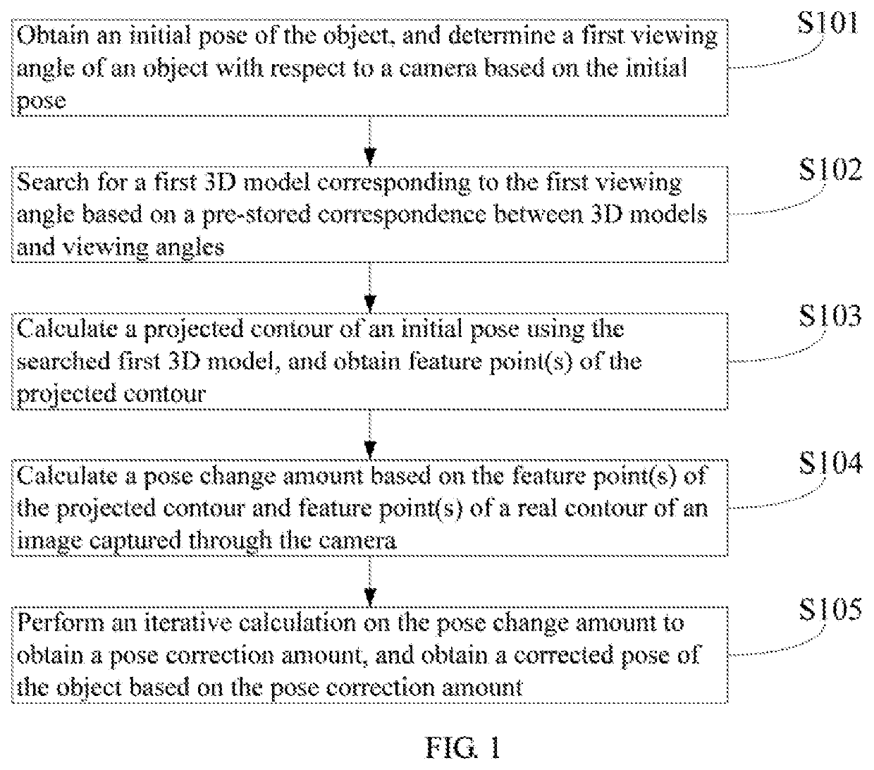
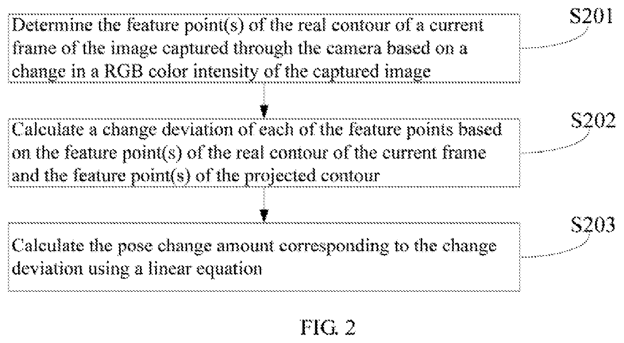
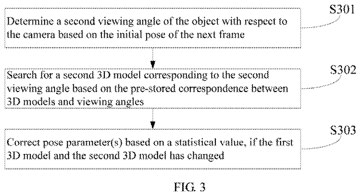
[0013]FIG. 1 is a flow chart of an object pose tracking method according to an embodiment of the present disclosure. In this embodiment, an object pose tracking method is provided. The method is a computer-implemented method...


PUM


Abstract

The present disclosure relates to robot technology, which provides an object pose tracking method and apparatus. The method includes: obtaining an initial pose of the object, and determining a first viewing angle of an object with respect to a camera based on the initial pose; searching for a first 3D model corresponding to the first viewing angle; calculating a projected contour of an initial pose using the searched first 3D model, and obtaining feature point(s) of the projected contour; calculating a pose change amount based on the feature point(s) of the projected contour and feature point(s) of a real contour; and performing an iterative calculation on the pose change amount to obtain a pose correction amount, and obtaining a corrected pose of the object based on the pose correction amount. In the calculation process, the 3D model can be selected to improve the calculation speed by fewer feature points.

Description

CROSS REFERENCE TO RELATED APPLICATIONS[0001]This application claims priority to Chinese Patent Application No. 201811510743.8, filed Dec. 11, 2018, which is hereby incorporated by reference herein as if set forth in its entirety.BACKGROUND1. Technical Field[0002]The present disclosure relates to robot technology, and particularly to an object pose tracking method and apparatus.2. Description of Related Art[0003]For an object with higher complexity such as an object having multiple sub-parts, or an object having multiple parts can be moved around a main body by rotating or shifting such as an object having tracks or a shovel, it will be more difficult to perform pose tracking on the object.[0004]When tracking an object by using features such as feature points or feature lines, it is possible to effectively track the pose of the object that is moved slowly or not in rotation. However, in the case that the speed of the object is increased, or there are many similar straight line featu...

Claims


Application Information

Patent Timeline
Patent Type & Authority Applications(United States)
IPC IPC(8): G06T7/73G06T7/246G06T7/90
CPCG06T7/251G06T7/75G06T7/90G06T7/246G06T7/70G06T2207/10012G06T2207/10024
Inventor XIONG, YOUJUNZHANG, WANLIPANG, JIANXIN
Owner UBTECH ROBOTICS CORP LTD
Learn More