

Sealed battery and assembled battery
a technology of assembled batteries and sealed batteries, which is applied in the direction of batteries, wound/folded electrode electrodes, sustainable manufacturing/processing, etc., can solve the problem of local temperature rising in the vicinity of the negative electrode side edge portion
Pending Publication Date: 2020-06-11
TOYOTA JIDOSHA KK
View PDF7 Cites 0 Cited by
- Summary
- Abstract
- Description
- Claims
- Application Information
AI Technical Summary
Benefits of technology
[0017]In the sealed battery according to the mode described above, the negative electrode side edge portion of the core portion is in close proximity with the negative electrode terminal and the positive electrode connecting portion is distanced from the positive electrode terminal. Using such sealed batteries as unit cells and electrically arranging the cells in series causes the positive electrode side edge p
Problems solved by technology
On the other hand, bringing the core portion too close to the negative electrode terminal may reverse temperatures of the positive electrode side edge port
Method used
View moreImage
Smart ImageViewing Examples

Examples
 PUM
 Abstract
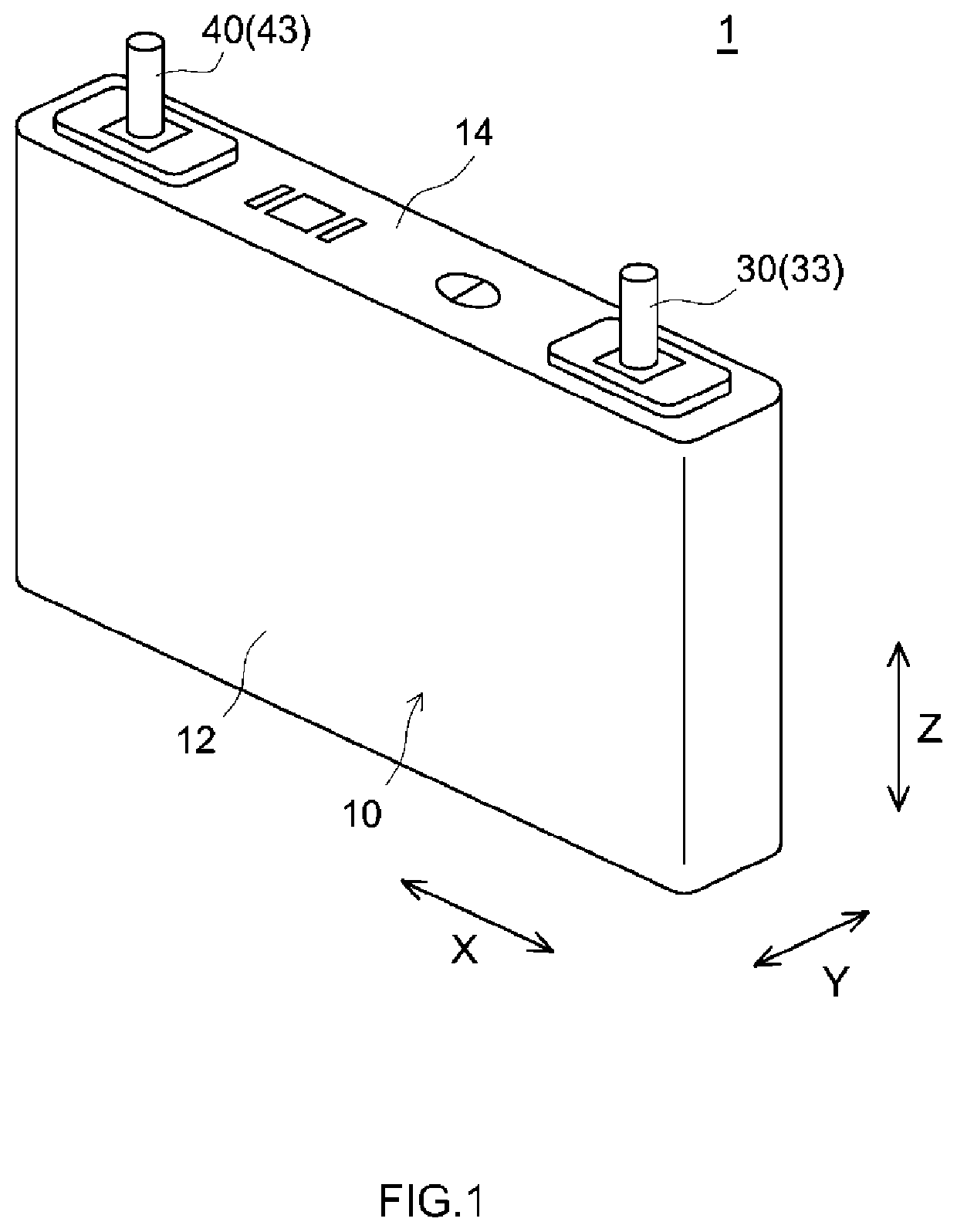
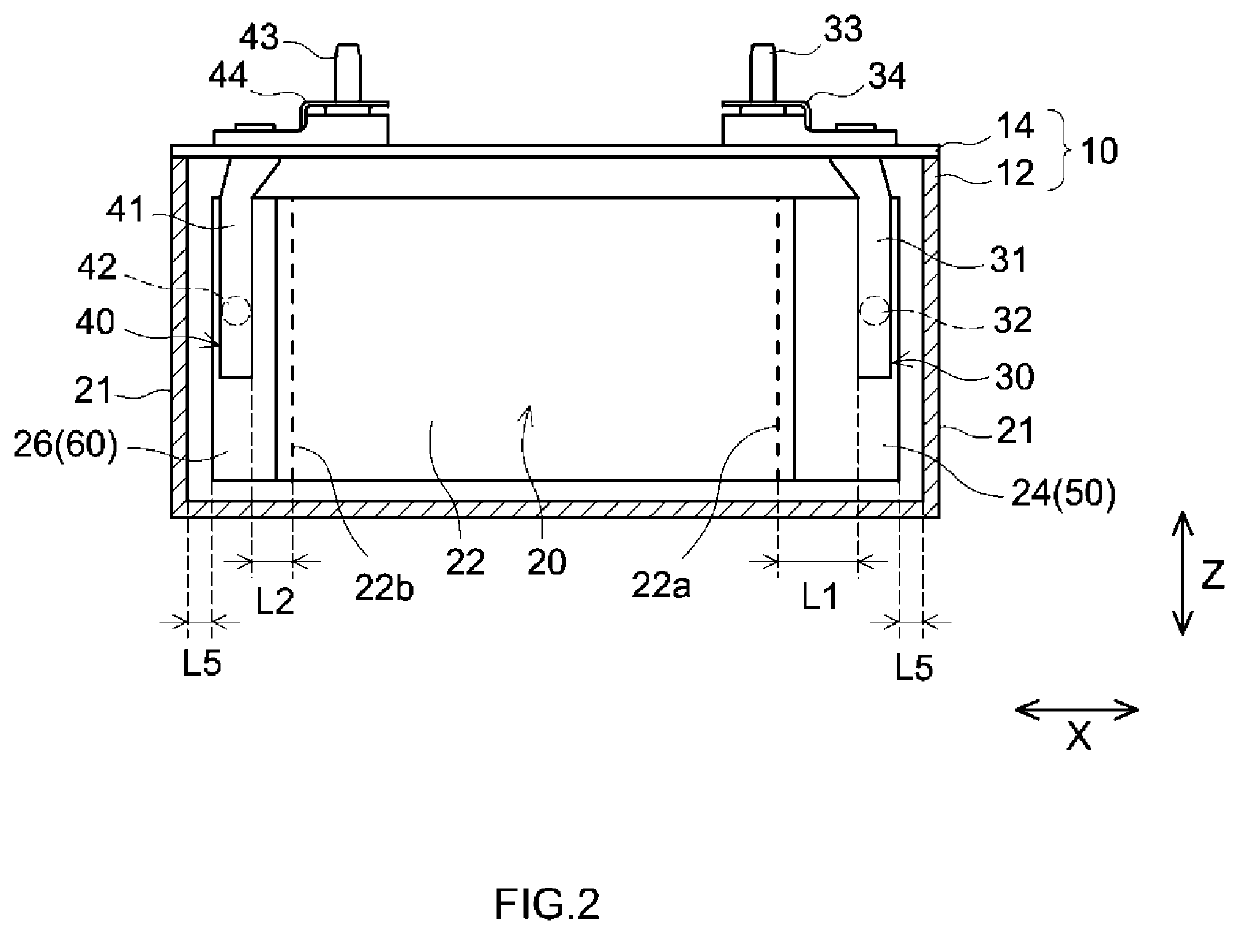
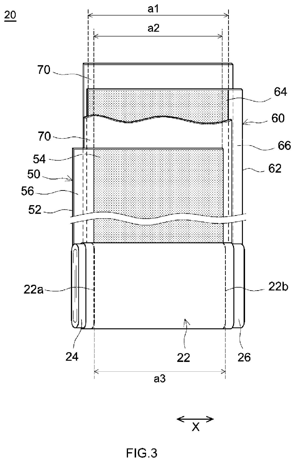
The present disclosure provides a technique that enables a contraction of a separator due to generation of heat by an electrode body to be appropriately suppressed and an internal short circuit due to a contraction of the separator to be preferably prevented. In a sealed battery 1 disclosed herein, a core portion 22 is formed such that a distance L1 and a distance L2 satisfy 1<L1/L2<1.8, the distance L1 being a shortest distance between a positive electrode side edge portion 22a that is a side edge portion of the core portion 22 on a side of a positive electrode connecting portion 24 and a side edge portion on a side of the core portion 22 of a positive electrode-connected location 32 and the distance L2 being a shortest distance between a negative electrode side edge portion 22b that is a side edge portion of the core portion 22 on a side of a negative electrode connecting portion 26 and a side edge portion on the side of the core portion 22 of a negative electrode-connected location 42. Accordingly, an occurrence of a localized temperature rise in a specific region can be suppressed and an internal short circuit in accordance with a thermal contraction of a separator can be more preferably prevented.
Description
CROSS REFERENCE TO RELATED APPLICATIONS[0001]The present application claims priority on the basis of Japanese Patent Application No. 2018-231018 filed in Japan on Dec. 10, 2018, the entire contents of which are incorporated herein by reference.BACKGROUND1. Technical Field[0002]The present disclosure is related to a sealed battery and an assembled battery including a plurality of the sealed batteries as unit cells.2. Description of the Related Art[0003]Lithium ion secondary batteries and other secondary batteries are growing in importance as vehicle-mounted power supplies and as power supplies for personal computers, mobile phones, and the like. In particular, lithium ion secondary batteries being lightweight and capable of attaining high energy density are widely used as high-output vehicle-mounted power supplies. A typical structure of such secondary batteries is a sealed battery.[0004]An example of the sealed battery will now be described with reference to FIG. 9. In a sealed batt...
Claims
Login to View More Application Information
Patent Timeline
 IPC IPC(8): H01M2/26H01M2/30H01M2/06H01M4/66H01M50/103H01M50/176H01M50/507H01M50/55H01M50/553H01M50/562
CPCH01M2/06H01M2004/027H01M2/30H01M4/662H01M2/263H01M2004/028H01M10/0413H01M4/13H01M4/661H01M50/553H01M50/55H01M50/176H01M50/507H01M50/562H01M50/103H01M2220/20H01M10/0431Y02E60/10Y02P70/50H01M10/0587H01M50/586H01M50/59H01M50/543H01M50/502H01M2220/30Y02T10/70H01M4/70H01M10/0585H01M50/505
InventorUMEMURA, KOJIKUSAMA, KAZUYUKI
OwnerTOYOTA JIDOSHA KK