Rotor and motor comprising same

a technology of rotating motors and rotating shafts, applied in the direction of dynamo-electric machines, magnetic circuit shapes/forms/construction, structural associations, etc., can solve problems such as vibration, and achieve the effect of greatly reducing the torque of coiling and reducing the width of the magn

Active Publication Date: 2020-06-11
LG INNOTEK CO LTD
View PDF0 Cites 1 Cited by
  • Summary
  • Abstract
  • Description
  • Claims
  • Application Information

AI Technical Summary

Benefits of technology

[0046]According to an embodiment, an advantageous effect is provided in that a cogging to

Problems solved by technology

Particularly, a torque ripple may be generated in a high-speed condition, a

Method used


Image

  • Rotor and motor comprising same
  • Rotor and motor comprising same
  • Rotor and motor comprising same

Examples


Embodiment Construction

[0061]Hereinafter, exemplary embodiments of the present invention will be described with reference to the accompanying drawings in detail. Purposes, specific advantages, and novel features of the invention will be made clear from the exemplary embodiments and the following detailed description in connection with the accompanying drawings. Terms and words used in this specification and claims are not to be interpreted as limited to commonly used meanings or meanings in dictionaries, and should be interpreted as having meanings and concepts which are consistent with the technological scope of the invention based on the principle that the inventors have appropriately defined concepts of terms in order to describe the invention in the best way. In the description of the invention, when it is determined that detailed descriptions of related well-known functions unnecessarily obscure the gist of the invention, the detailed descriptions thereof will be omitted.

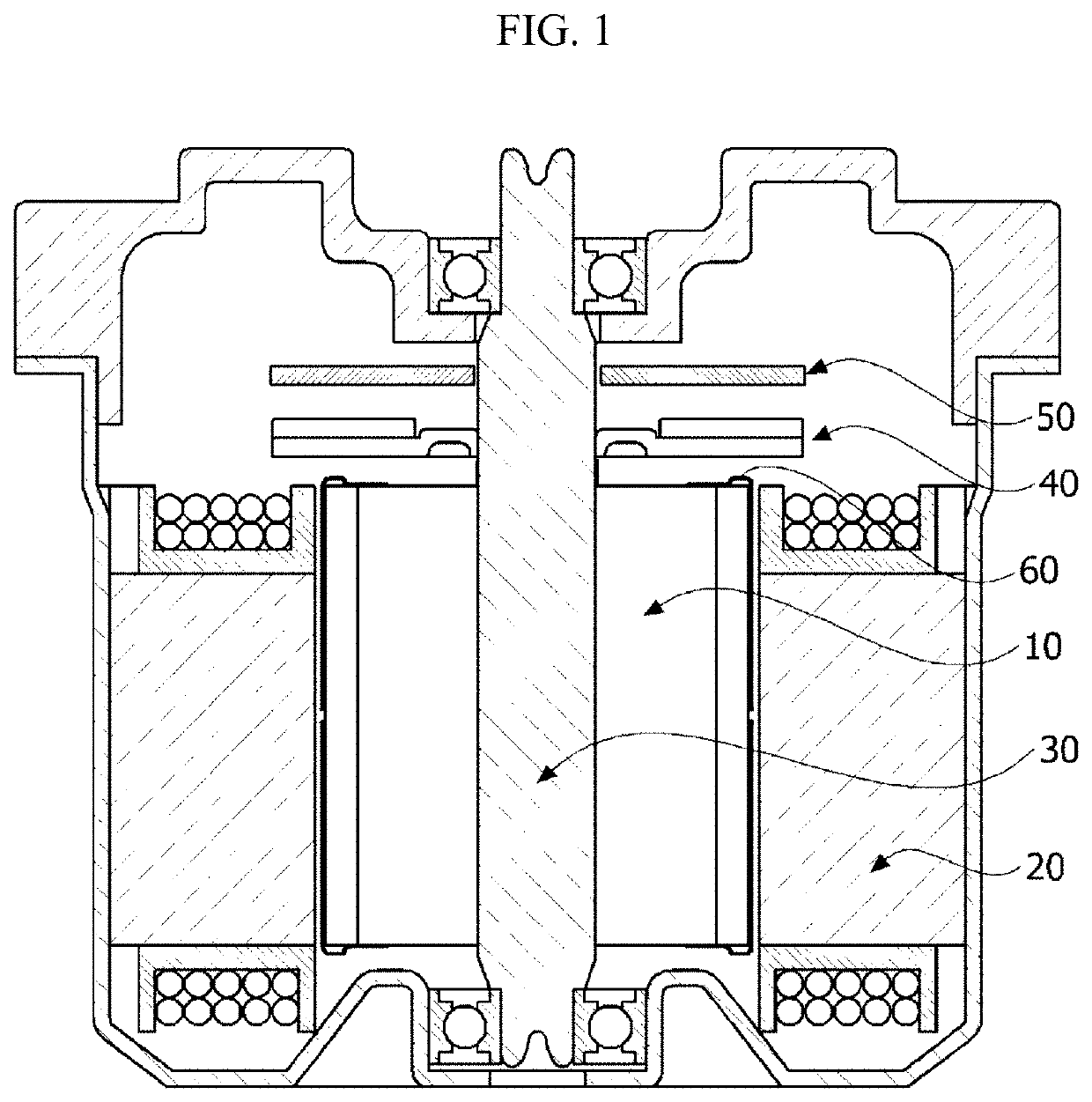
[0062]FIG. 1 is a view illust...


PUM


Abstract

The present invention provides rotor including: a rotor core having a cylindrical shape; and a plurality of magnets disposed to surround an outer circumferential surface of the rotor core, wherein the magnet includes an inner circumferential surface in contact with the outer circumferential surface of the rotor core, when a first angle is defined by dividing an angle formed by the outer circumferential surface of the rotor core by the number of magnets, a second angle is formed by a first extension line and a second extension line which extend from both end points of the inner circumferential surface of the magnet to a center point of the rotor core on cross sections of the rotor core and the magnet, and a ratio of the second angle to the first angle is in a range of 0.87 to 0.93, thereby providing an advantageous effect of greatly reducing a cogging torque by decreasing a width of the magnet to double a cogging main degree.

Description

TECHNICAL FIELD[0001]The present invention relates to a rotor and a motor including the same.BACKGROUND ART[0002]An electric power steering (EPS) system is an apparatus which secures turning stability of a vehicle and rapidly provides a restoring force so that a driver can safely travel. The EPS system drives a motor using an electronic control unit (ECU) according to traveling conditions which are detected by a vehicle speed sensor, a torque angle sensor, and a torque sensor to control driving of a steering shaft of the vehicle.[0003]The motor includes a stator and a rotor. The stator may include teeth which form a plurality of slots, and the rotor may include a plurality of magnets facing the teeth. The adjacent teeth are disposed to be spaced apart from each other to form a slot open. Here, a cogging torque may be generated due to a difference in magnetic permeability between the stator formed of a metal, and the slot open, which is an empty space when the rotor rotates. Since su...

Claims


Application Information

Patent Timeline
IPC IPC(8): H02K1/27H02K29/03
CPCH02K2213/03H02K1/278H02K29/03H02K1/16H02K11/215H02K3/34
Inventor WOO, SHUNG HUNLEE, JUNG KYU
Owner LG INNOTEK CO LTD
Why Eureka
Try Eureka