Riding mower

Active Publication Date: 2020-06-18
KUBOTA LTD
View PDF0 Cites 0 Cited by
  • Summary
  • Abstract
  • Description
  • Claims
  • Application Information

AI Technical Summary

Benefits of technology

[0013]With the above-described arrangement, a cutting overlap line as a virtual line for indicating a cutting overlap is located downwardly of the overlap mark created by the invention. As this overlap mark is closer to the ground surface, thus being closer to the grass surface, than the vehicle body frame, the driver, with using this overlap mark as a target or “criterion”, can estimate the cutting overlap line easily and accurately. Moreover, in case the mower deck is disposed forwardly of the front wheels (i.e. the case of a front mower), the overlap mark is located forwardly of the front wheels, so the possibility of the driver's view viewing the overlap mark being blocked by some component of the mower is low. Further, in case the mower deck is disposed between the front wheels and the rear wheels (i.e. the case of a mid-mount mower), as the overlap mark is located forwardly of the front wheels, the possibility of the driver's view viewing the overlap mark being blocked by some component of the mower is low in this case also.
[0014]The cutting guide device employed in the invention can be a mechanical guide assembly, an optical guide assembly, a fluid spray guide assembly, etc. Preferably, the mechanical guide assembly can employ a universal arm mechanism capable of maintaining a make

Problems solved by technology

If the cutting overlap is too large, this results in disadvantageous reduction the substantial working width, thus, deterioration in the work efficiency.
On the other hand, if the cutting overlap is too small, the cutting leftover tends to occur.
Also, in the event of

Method used


Image

  • Riding mower
  • Riding mower
  • Riding mower

Examples


Example

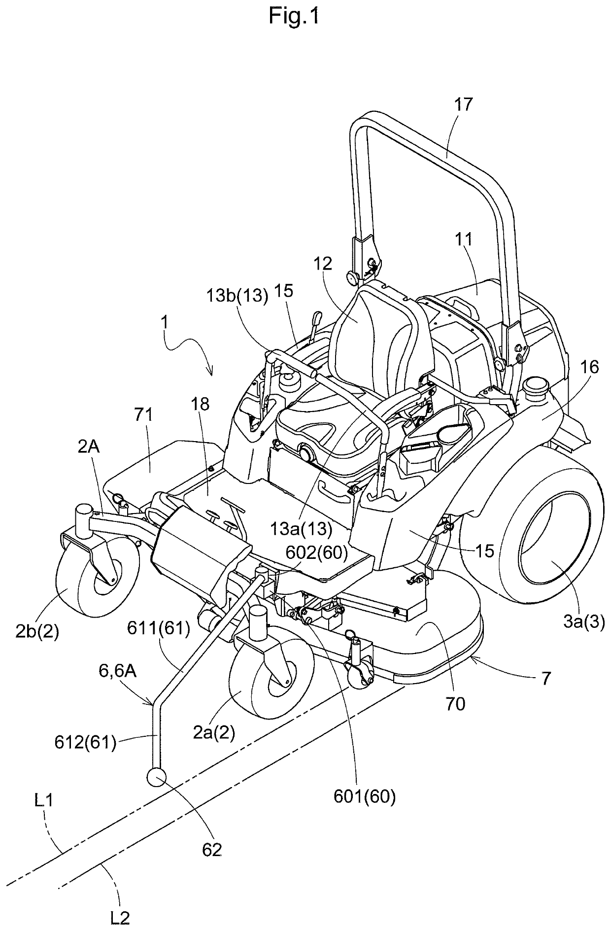
[0022]Next, a mower according to the invention will be explained with reference to the accompanying drawings. In the following detailed description, unless indicated explicitly otherwise, a word “front” means the front (forward) side with respect to a vehicle body front / rear direction (traveling direction). A word “rear” means the rear (rearward or reverse) side with respect to the vehicle body front / rear direction (traveling direction). Further, a language “left / right direction” or “lateral direction” means a vehicle body transverse direction (vehicle body width direction) perpendicular to the vehicle body front / rear direction. Also, a word “upper” and a word “lower” respectively refer to positional relationship in the perpendicular direction (vertical direction) of the vehicle body, indicating relationship in terms of ground clearance height.

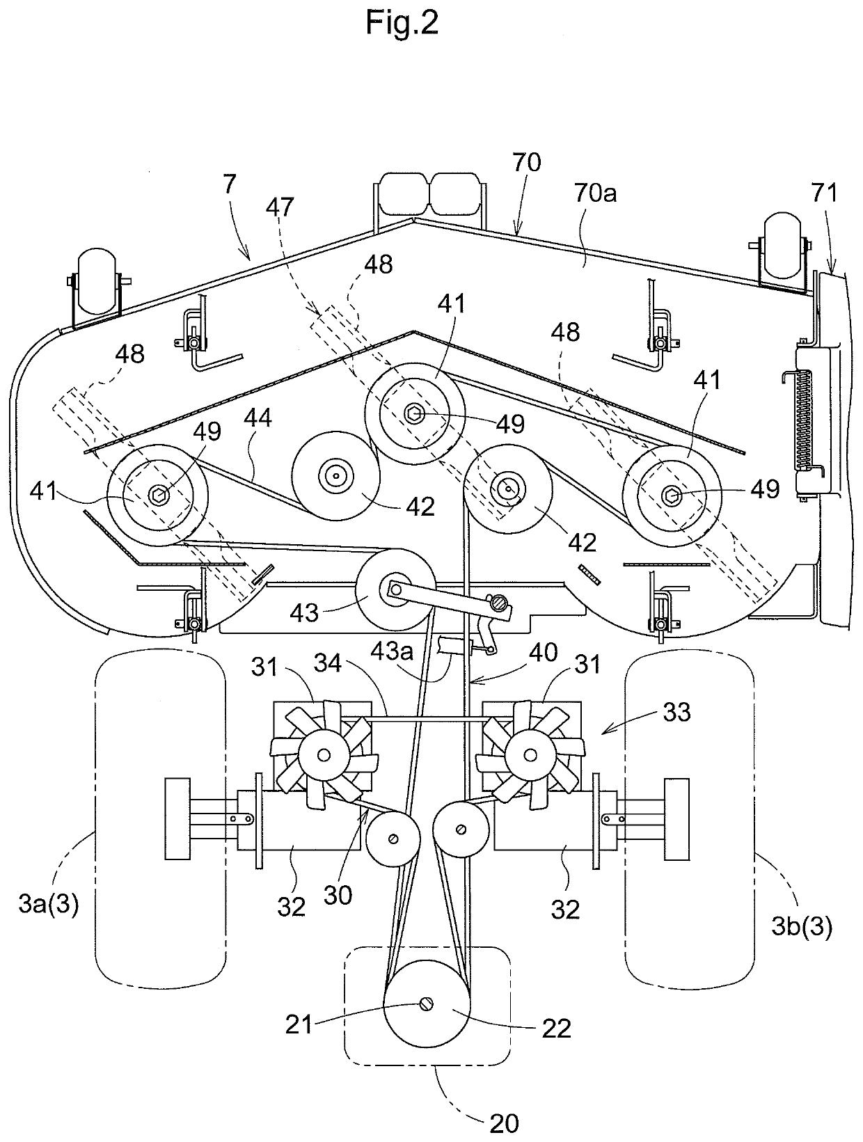
[0023]The mower, as shown in FIG. 1 and FIG. 2, includes a vehicle body frame 1 supported on the ground surface by a front wheel unit 2 as a ...


PUM


Abstract

A riding mower includes front wheels and rear wheels that support a vehicle body frame on the ground surface, a driver's seat disposed upwardly of the vehicle body frame, a mower deck disposed downwardly of the vehicle body frame and a cutting guide device configured to create an overlap mark that hints a cutting overlap line at a position forwardly of the front wheels and the mower deck and closer to the ground surface than the vehicle body frame.

Description

TECHNICAL FIELD[0001]This invention relates to a riding mower including a driver's seat disposed upwardly of a vehicle body frame supported on the ground surface by front wheels and rear wheels and a mower deck disposed downwardly of the vehicle body frame.BACKGROUND ART[0002]A riding mower effects, while traveling, a grass cutting operation by rotating a blade disposed inside a mower deck. In an operation of cutting grass (lawn) in a golf course or a ballpark, a straight traveling route or a traveling route having a large curvature radius is often employed. In this, when a grass cutting operation is to be made in a uncut area adjacent a cut area, a cutting overlap is implemented on the side of the cut area in order to avoid cutting leftover. If the cutting overlap is too large, this results in disadvantageous reduction the substantial working width, thus, deterioration in the work efficiency. On the other hand, if the cutting overlap is too small, the cutting leftover tends to occu...

Claims


Application Information

Patent Timeline
IPC IPC(8): A01D34/82A01D34/00A01D34/64
CPCA01D2101/00A01D34/82A01D34/006A01D34/64A01D34/001
Inventor TAKAOKA, MASAKI
Owner KUBOTA LTD
Why Eureka
Try Eureka