Image processing device, image processing method, and program
a technology of image processing and image processing method, applied in the field of image processing device, image processing method, and program, can solve the problems of inability to perform the immediate processing of each image, inability to disclose the processing in the case of moving cameras, and inability to execute the processing for a stationary image. , to achieve the effect of removing or reducing the blur
- Summary
- Abstract
- Description
- Claims
- Application Information
AI Technical Summary
Benefits of technology
Problems solved by technology
Method used
Image


Examples
first embodiment
5. (First Embodiment) Configuration and Processing of Image Processing Device Corresponding to Configuration A
[0229]Next, specific configuration and processing of an image processing device corresponding to the configuration A described with reference to FIG. 7 will be described as a first embodiment of the image processing device of the present disclosure.
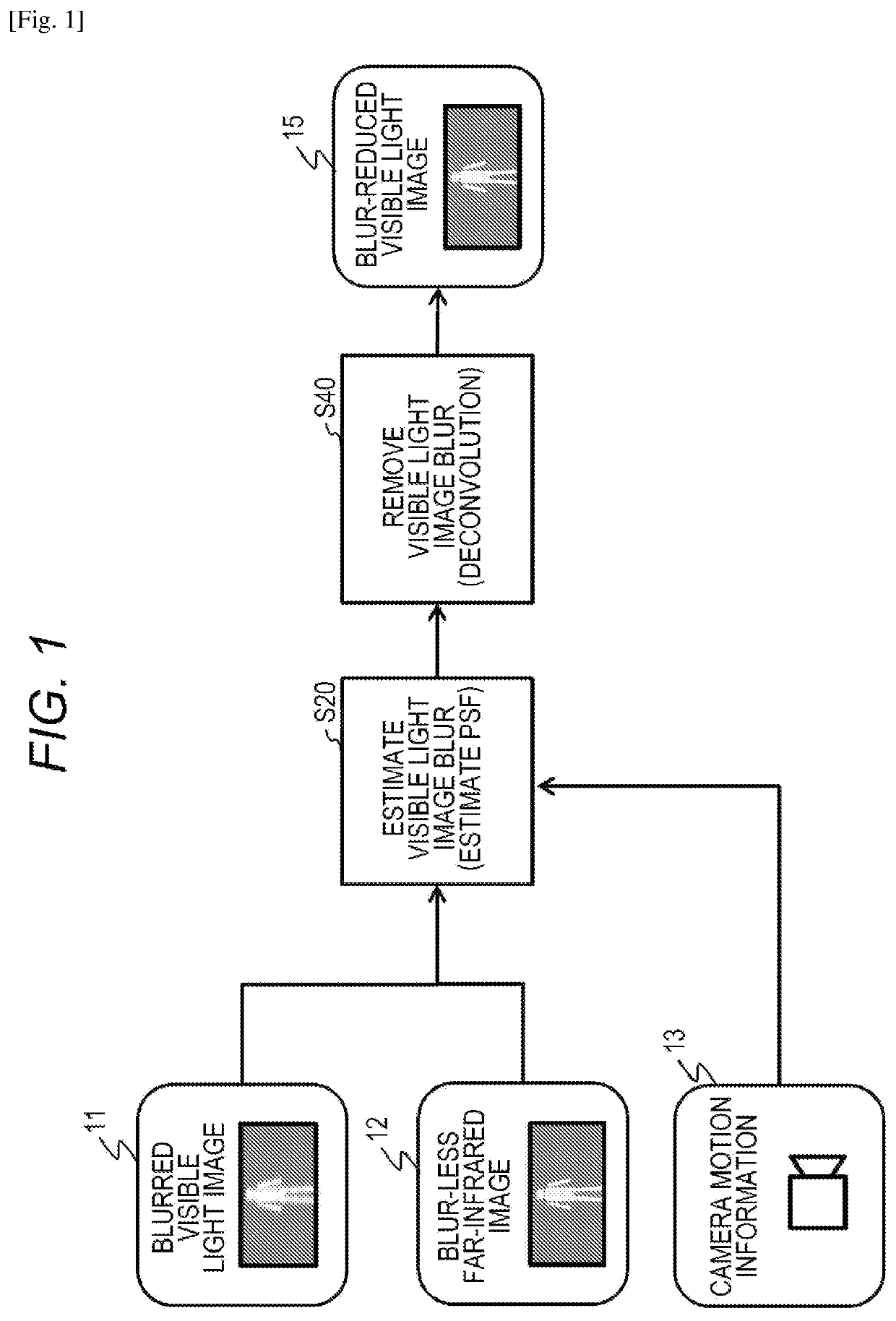
[0230]As described earlier with reference to FIG. 7, the configuration A is a configuration in which camera motion-based blur estimation information based on camera motion information is, after image-based blur estimation using a visible light image and a far-infrared image, utilized to execute final integrated blur estimation.
[0231]Note that the processing form of the integrated blur (Eall) estimation processing of the configuration A includes the following two types:
[0232](A1) a configuration in which an integrated blur (Eall) to be applied or selected is switched between an image-based blur (Et) and a camera motion-based blur (...
second embodiment
6. (Second Embodiment) Configuration and Processing of Image Processing Device Corresponding to Configuration B
[0444]Next, specific configuration and processing of an image processing device corresponding to the configuration B described with reference to FIG. 7 will be described as a second embodiment of the image processing device of the present disclosure.
[0445]As described earlier with reference to FIG. 7, the configuration B is a configuration in which image-based blur estimation using a visible light image and a far-infrared image and camera motion-based blur estimation based on camera motion information are executed in combination to execute integrated blur estimation.
[0446]Note that any of the following two types of processing is executed in the processing of generating an integrated blur (Eall) in the configuration B:
[0447](B1) the processing of selecting a filter to be applied to the far-infrared image, i.e., a filter for generating a blur (defocusing), on the basis of a c...
third embodiment
7. (Third Embodiment) Configuration and Processing of Image Processing Device Corresponding to Configuration A+C
[0675]Next, the configuration and processing of an image processing device with the configuration (A+C) described with reference to FIG. 8, i.e., an image processing device configured, with the configuration A as a basic configuration, to further calculate the degree of reliability of a filter (blur) estimation result to perform blur removing processing according to the degree of reliability, will be described as a third embodiment of the image processing device of the present disclosure.
[0676]The configuration A is a configuration in which an integrated filter (Eallf) of an image-based filter (Etf) and a camera motion-based filter (Ecf) is estimated to apply an inverse filter with characteristics opposite to those of the integrated filter (Eallf) to a blurred visible light image.
[0677]The configuration A+C described below as the third embodiment is a configuration in whic...
PUM
 Abstract
Description
Claims
Application Information
 - R&D
- Intellectual Property
- Life Sciences
- Materials
- Tech Scout
- Unparalleled Data Quality
- Higher Quality Content
- 60% Fewer Hallucinations
Browse by: Latest US Patents, China's latest patents, Technical Efficacy Thesaurus, Application Domain, Technology Topic, Popular Technical Reports.
© 2025 PatSnap. All rights reserved.Legal|Privacy policy|Modern Slavery Act Transparency Statement|Sitemap|About US| Contact US: help@patsnap.com