Exhaust gas aftertreatment system for an internal combustion engine

an exhaust gas aftertreatment and internal combustion engine technology, which is applied in the direction of engines, machines/engines, mechanical equipment, etc., can solve the problems of difficult to provide an ageing-resistant three-way coating on a particulate filter for all markets, configuration to be much larger, and light-off problems, so as to improve the light-off, optimize the catalytic conversion in the first catalytic converter, and achieve positive heat balance

Active Publication Date: 2020-07-02
VOLKSWAGEN AG
View PDF0 Cites 2 Cited by
  • Summary
  • Abstract
  • Description
  • Claims
  • Application Information

AI Technical Summary

Benefits of technology

[0010]The advantage of the invention is that, since the exhaust gas flows around the first catalytic converter through the flow-around area, the first catalytic converter undergoes a temperature increase due to heat exchange with the warm or hot exhaust gas. This warms up the first catalytic converter. This improves the light-off and, as a result, the catalytic conversion in the first catalytic converter is optimized. Moreover, a positive heat balance is achieved since the exhaust gas heat is energetically utilized to heat up the first catalytic converter more quickly to the actively effective catalytic temperature range. Moreover, such a version as well as the additional ones can be implemented package-neutrally and are also cost-effective. This simplifies the regenerations. Furthermore, the invention can be ideally implemented for gaseous pollutants in motor vehicles that belong to high flywheel classes. It is especially advantageous that the first catalytic converter can be uniformly heated owing to the flow-around.
[0011]The features described in the dependent claims yield advantageous improvements and non-trivial refinements of the exhaust gas aftertreatment system cited in the independent claim.
[0012]In a preferred embodiment, the flow-around area is formed adjacently around a lateral surface of the first catalytic converter. Catalytic converters are usually configured to be cylindrical. The fact that the exhaust gas flows around the cylinder lateral surface advantageously ensures an especially uniform heating of the first catalytic converter.
[0013]In a preferred embodiment of the invention, it is provided for the first catalytic converter to be installed in a housing and for the flow-around area to be formed by a space between the housing and the first catalytic converter. This allows a simple and cost-effective implementation of the flow-around area so that the housing walls hold the exhaust gas in the flow-around area and press it—at least by means of gas pressure—into the first catalytic converter. The housing walls can also function as deflection means that serve to deflect the exhaust gas stream.
[0014]In a preferred embodiment of the invention, it is provided for a deflection device to be positioned at an outlet side of the first catalytic converter, said deflection device being configured to feed the exhaust gas from the outlet side of the first catalytic converter to the flow-around area of the first catalytic converter. Such a deflection device can be, for example, a metal plate or a baffle plate that imparts the exhaust gas with a desired flow direction. For example, the deflection device can form an opening that is slanted in the deflection direction. A deflection device can improve the flow-around properties of the exhaust gas. In particular, a stream can suitably flow onto the first catalytic converter so that the exhaust gas flows uniformly through the flow-around area. For example, the stream can flow onto a lateral surface of the first catalytic converter in such a way that some of the exhaust gas flows around above the surface and some of the exhaust gas flows around below the surface and, in particular, the flow around the lateral surface is uniform.
[0015]In another preferred embodiment, it is provided for the first catalytic converter to have a first exhaust gas conveying direction which allows the exhaust gas to pass through, and whereby the second catalytic converter has a second exhaust gas conveying direction which allows the exhaust gas to pass through, and whereby the first catalytic converter is oriented relative to the second catalytic converter in such a way that the first and the second exhaust gas conveying directions are oriented between 45° and 135° relative to each other, more preferably between 60° and 120° relative to each other, especially preferably perpendicular to each other. In this manner, an arrangement is created that is suitable to allow a deflection so that the exhaust gas can flow through as well as around the first catalytic converter.

Problems solved by technology

Moreover, it is currently difficult to provide an ageing-resistant three-way coating on a particulate filter for all markets.
A drawback of this, however, is that, if there is only one three-way catalytic converter, it has to be configured to be much larger since the uncoated particulate filter cannot contribute in the conversion of the gaseous components.
This, in turn, gives rise to light-off problems.
Up until now, these problems have been remedied in a complicated manner, namely, by creating additional installation spaces, by using more precious metal on the three-way catalytic converter in the case of an uncoated particulate filter, or by reducing the gaseous raw emissions, possibly entailing disadvantages in terms of the CO2 emissions.

Method used


Image

  • Exhaust gas aftertreatment system for an internal combustion engine

Examples


Embodiment Construction

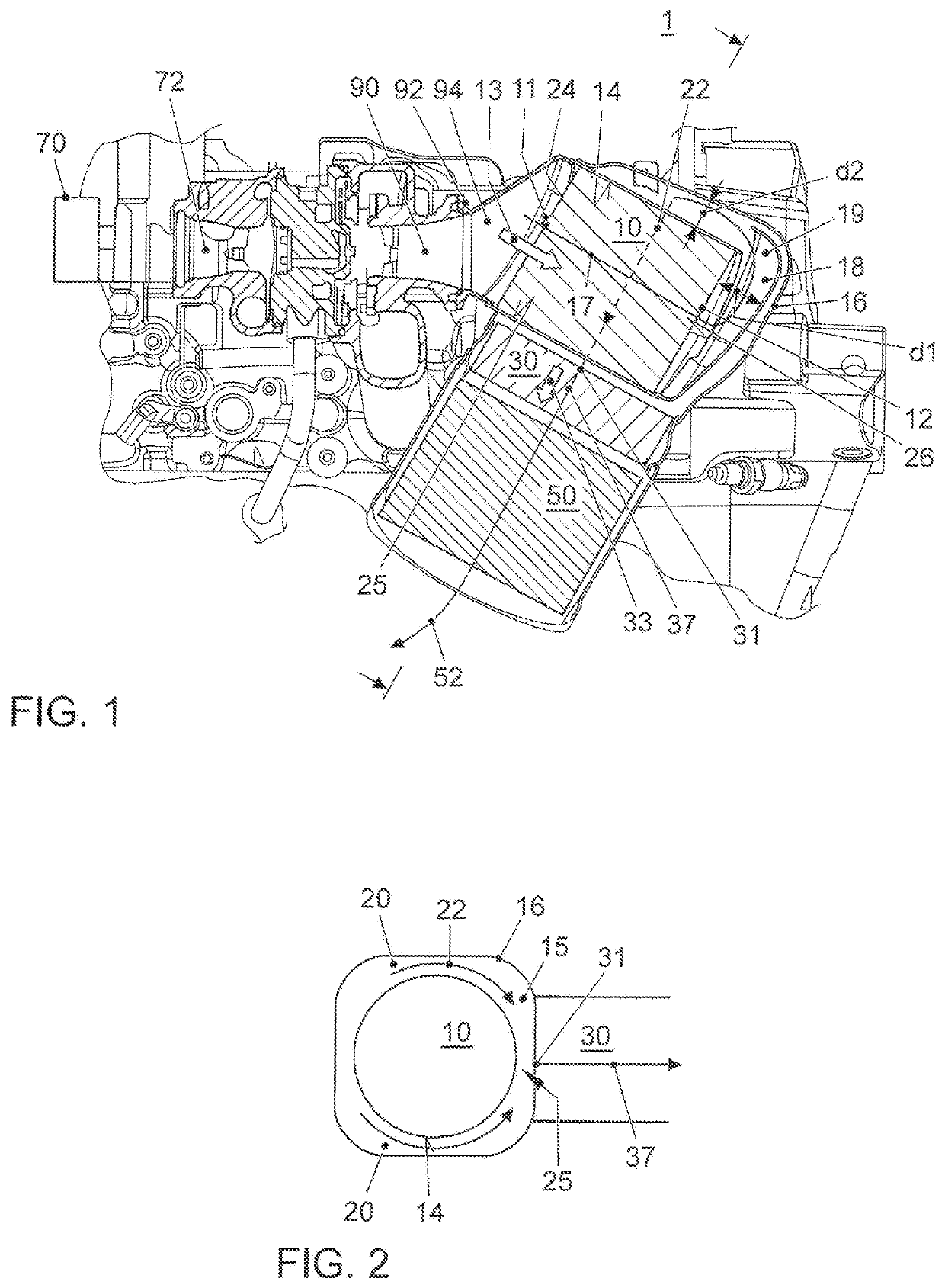
[0028]FIG. 1 shows an exemplary embodiment of an exhaust gas aftertreatment system 1 according to the invention. Other additional components are shown in the present depiction in which the exhaust gas aftertreatment system 1 has been installed, whereby the technical depiction serves merely for illustration purposes and the invention is not limited to such an implementation. Exhaust gas from an internal combustion engine 70 is fed to the exhaust gas aftertreatment system 1. In this context, the internal combustion engine 70, preferably a gasoline engine, is shown schematically. Moreover, a turbocharger having a compressor 72 and a turbine 90 is shown by way of example. Via a connecting flange 92, for example, an inlet funnel 94 adjoins the turbine 90. In this embodiment, by way of example, the exhaust gas is fed to the exhaust gas aftertreatment system 1 via the inlet funnel 94. In this exemplary embodiment, the inlet funnel 94 is slanted on the outlet side and it deflects the exhaus...


PUM


Abstract

The invention relates to an exhaust gas aftertreatment system for an internal combustion engine comprising a first catalytic converter that has a first exhaust gas inlet to admit the exhaust gas into the first catalytic converter and has an exhaust gas outlet positioned on the opposite side, also comprising a second catalytic converter that is arranged downstream from the first catalytic converter and that is flow-connected to the first catalytic converter in order to allow the exhaust gas to pass from the first catalytic converter into the second catalytic converter and that likewise has a second exhaust gas inlet that is at a physical distance from the exhaust gas outlet of the first catalytic converter. The exhaust gas aftertreatment system also comprises a particulate filter that is arranged downstream from the second catalytic converter and that is flow-connected to the second catalytic converter in order to allow the exhaust gas to pass from the second catalytic converter into the particulate filter. A flow-around area is formed adjacent to an outer surface of the first catalytic converter in which the exhaust gas flows from the exhaust gas outlet to the second exhaust gas inlet into the second catalytic converter.

Description

CROSS REFERENCE TO RELATED APPLICATION[0001]This application claims priority from German Patent Application No. 10 2018 133 634.9, filed Dec. 27, 2019, the entire contents of which are incorporated by reference.FIELD OF THE INVENTION[0002]The invention relates to an exhaust gas aftertreatment system for an internal combustion engine.BACKGROUND OF THE INVENTION[0003]Due to the high levels of efficiency of gasoline engines, the regeneration of a particulate filter located in the undercarriage requires special driving cycles. In order to regenerate a particulate filter, there is a need for exhaust gas temperatures of, for example, more than 600° C. in the particulate filter. In this case, the particulate filter has to be situated in a position near the engine since this causes higher temperatures to be present in the particulate filter. Moreover, it is currently difficult to provide an ageing-resistant three-way coating on a particulate filter for all markets. Consequently, in order to...

Claims


Application Information

Patent Timeline
Patent Type & Authority Applications(United States)
IPC IPC(8): F01N3/035F01N13/00F01N13/18
CPCF01N3/035F01N13/009F01N13/1888F01N3/021F01N3/20F01N3/2807F01N3/2825F01N3/2006F01N3/101F01N13/0093F01N2340/02F01N2470/08F01N2330/02F01N2330/06F01N2260/08F01N2240/20Y02A50/20F01N13/0097
Inventor CAR, ONUR ULASPAULOVSKY, MARKUS
Owner VOLKSWAGEN AG
Why Eureka
Try Eureka