System and method for stability-based constrained numerical calibration of material models

Pending Publication Date: 2020-07-02
DASSAULT SYSTEMES SIMULIA CORP
View PDF0 Cites 7 Cited by
  • Summary
  • Abstract
  • Description
  • Claims
  • Application Information

AI Technical Summary

Benefits of technology

The patent describes a computer simulation system that uses an experimental test data set to calibrate a material model for use in a computer simulation. The system includes a memory to store the experimental test data set, a processor to display the data set to a user and identify the material model, an iterative optimization process to calibrate the material model, and a constraint based on Drucker's stability criterion. The calibrated material model is then assigned to a component of a simulation model, which performs a simulation using the stable material model and parameters. The technical effect of this patent is to provide a reliable and accurate material model for computer simulation, which can predict the response of a real-world equivalent during a real-world experiment.

Problems solved by technology

Such experimentally collected data sets are typically not directly used in numerical simulations.
However, such known simulation software systems may generate an unstable material model.
For example, a material model for a rubber band may complete successfully for a deformation of the rubber band at twice its natural length, but that model may be unstable for deformations beyond three times the rubber band's length.
When a user (e.g., an engineer, scientist) executes a component simulation that uses the unstable material model in the simulation software system, the simulation may not succeed (e.g., may not run to completion).
The user may be left wondering why the simulation did not succeed, requiring the user to investigate various failure potentials before potentially discovering that the unstable material model caused the failure.
Even if the user is informed that the material model is unstable, that information does not necessarily implicate the material model in larger simulations, and also does not provide a solution, just one clue as to what may be causing the failure.

Method used


Image

  • System and method for stability-based constrained numerical calibration of material models
  • System and method for stability-based constrained numerical calibration of material models
  • System and method for stability-based constrained numerical calibration of material models

Examples


Embodiment Construction

[0017]The following detailed description illustrates embodiments of the disclosure by way of example and not by way of limitation. It is contemplated that the disclosure has general application to computer simulation with material models.

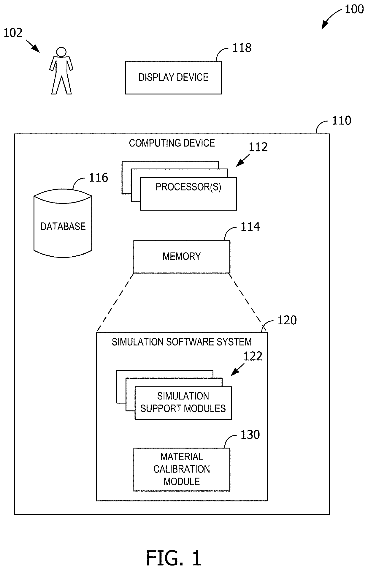
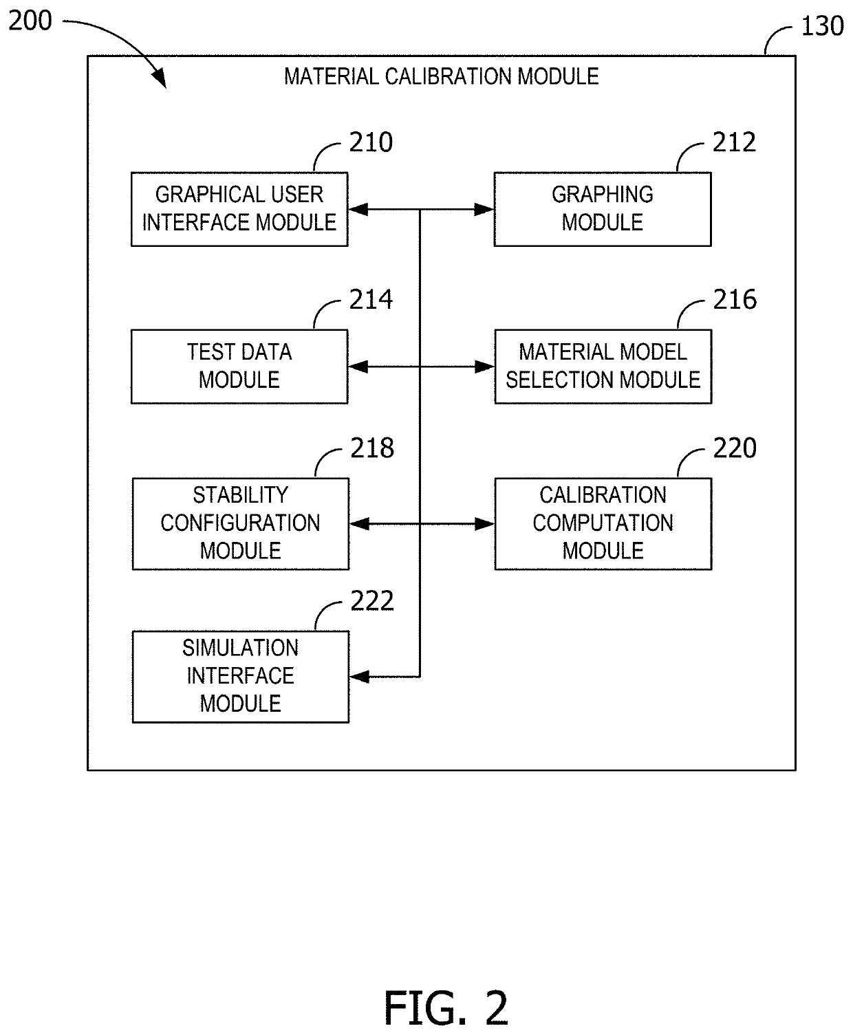
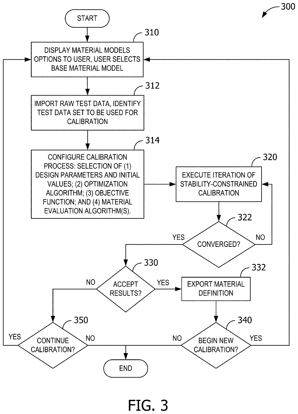
[0018]A simulation system provides a material calibration module and associated methods that, as described herein, determine a stable material model for use in simulating a particular real-world material. During a material model calibration process, the material calibration module determines parameter values for a base material constitutive model such that the resulting material model (“calibrated material model”) is configured to be stable across certain strain ranges.

[0019]During configuration, the material calibration module provides a graphical user interface (“GUI”) through which a user (e.g., an engineer, a product tester) provides a set of material test data (e.g., strain-stress test data for one or more deformation modes) from a real-world l...


PUM


Abstract

A computer simulation system is configured to display to a user a graphical user interface to allow the user to import experimental test data, identify a material model that includes one or more parameters to be calibrated during a material model calibration process, perform an iterative optimization process to calibrate the material model, the iterative optimization process uses an optimization algorithm that enforces a constraint based on Drucker's stability criterion across one or more predetermined strain ranges to generate a calibrated material model, assign the calibrated material model to a component of a simulation model based on input from the user, a real-world equivalent of the component being made of the physical material, and perform a simulation that includes the component, the simulation using the stable material model and stable set of parameters to simulate response of the real-world equivalent during the simulation.

Description

BACKGROUND[0001]This disclosure relates generally to simulation systems and, more particularly, to systems and methods for stability-based constrained numerical calibration of material models in computer simulations.[0002]Material constitutive models are mathematical models which attempt to replicate the behavior of a real material in a computer simulation software system. Such material models represent a significant aspect of the simulation software systems. A material constitutive model may be used to simulate a simple component involving the material, such as a component of a vehicle chassis, or a more complex assembly such as an entire vehicle chassis.[0003]Some known systems use experimental data derived from real-world tests to generate a material constitutive model for a particular material. Real materials are commonly tested in a laboratory under specific loading conditions. During such tests, a specimen made of the real material is subjected to one or more deformation modes...

Claims


Application Information

Patent Timeline
IPC IPC(8): G06F17/50G06F3/0484
CPCG06F30/23G06F2203/04803G06F3/0482G06F3/04847G06F2111/10G16C60/00G06F30/20G06F2113/26
Inventor COJOCARU, DANWOHLEVER, JAMES CHRISTOPHERDALRYMPLE, TOD OLAN
Owner DASSAULT SYSTEMES SIMULIA CORP
Why Eureka
Try Eureka