Tubular linear motor

a linear motor and tube technology, applied in the direction of dynamo-electric machines, electrical apparatus, magnetic circuits, etc., can solve the problem of difficult to obtain a large thrust, and achieve the effect of suppressing magnetic saturation and improving thrus

Active Publication Date: 2020-07-02
KYB CORP
View PDF0 Cites 0 Cited by
  • Summary
  • Abstract
  • Description
  • Claims
  • Application Information

AI Technical Summary

Benefits of technology

[0006]Thus, an object of the present invention is to provide a tubular linear motor capable of suppressing magnetic saturation to improve thrust.
[0007]To achieve the foregoing object, a tubular linear motor of the present invention includes a core that has a tubular yoke and a plurality of teeth which are annular and provided at intervals in an axial direction on an outer periphery of the yoke; a winding mounted in a slot between the teeth; and a field magnet that is tubular, into which the core is inserted movably in the axial direction, and having N poles and S poles alternately arranged in the axial direction, wherein an axial width of a yoke-side inner peripheral edge of the teeth is larger than an axial width of an outer peripheral edge of the teeth. In a tubular linear motor thus configured, a magnetic circuit cross-sectional area which is large in comparison with a conventional tubular linear motor can be secured, and magnetic saturation when the winding is electrified can be suppressed.

Problems solved by technology

Thus, the magnetic circuit cross-sectional area of the teeth T is also maximum at the outer peripheral edge to of the teeth T and minimum at the inner peripheral edge ti of the teeth T. In a conventional tubular linear motor of this kind, even when the winding is electrified, because the magnetic circuit cross-sectional area at the inner peripheral edge ti of the teeth T is small, the magnetic flux is saturated at the inner peripheral edge ti, which has made obtaining a large thrust difficult.

Method used


Image

  • Tubular linear motor
  • Tubular linear motor
  • Tubular linear motor

Examples


first embodiment

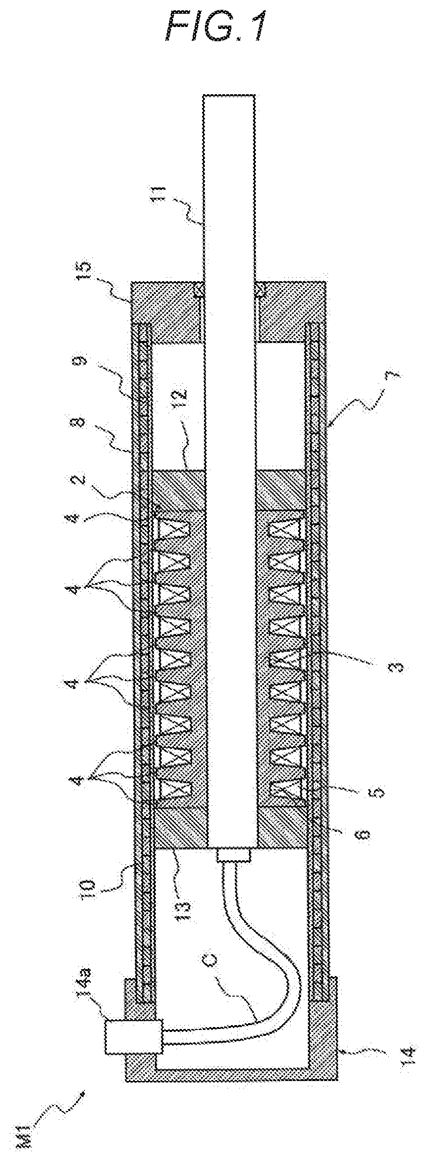
[0019]The tubular linear motor M1 according to the first embodiment includes, as illustrated in FIG. 1, a core 2 that has a tubular yoke 3 and a plurality of annular teeth 4 provided on an outer periphery of the yoke 3; a winding 5 mounted between the teeth 4, 4; and a field magnet 7 that is tubular and into which the core 2 is inserted movably in the axial direction.

[0020]Each part of the tubular linear motor M1 will be described in detail hereinbelow. The core 2 includes a cylindrical yoke 3, and a plurality of teeth 4 which are annular and provided at intervals in an axial direction on the outer periphery of the yoke 3, and constitutes a movable element in the present embodiment.

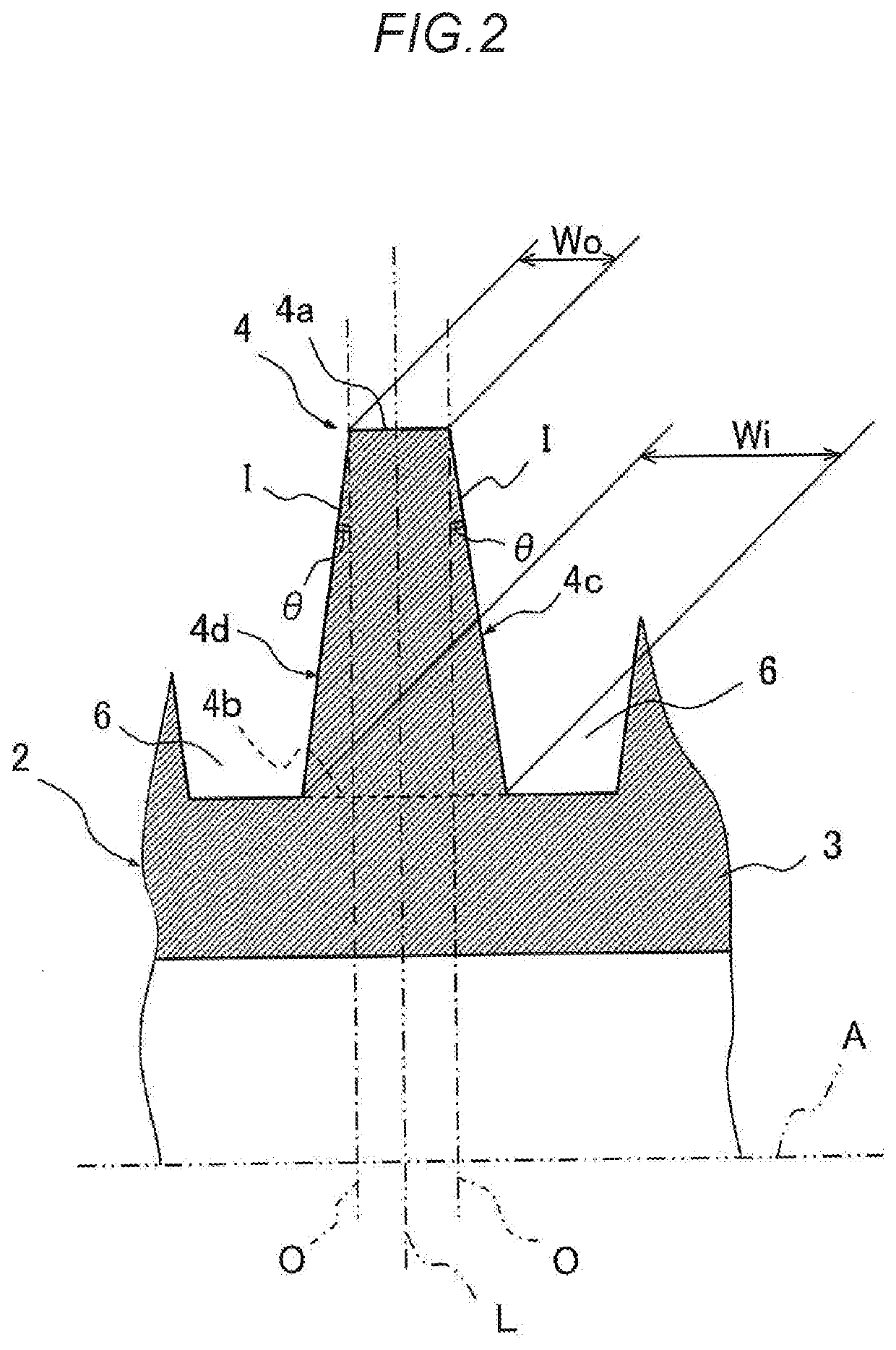
[0021]The yoke 3 is cylindrical as mentioned above and a wall thickness is secured such that, even when the teeth 4 are cut somewhere between the inner periphery and outer periphery thereof using a cylinder centered on an axis A of the core 2 (see FIG. 2), the cross-sectional area of the yoke 3 is equal t...

second embodiment

[0041]The tubular linear motor M2 according to the second embodiment includes, as illustrated in FIG. 6 and similarly to the tubular linear motor 1 according to the first embodiment, a core 21 that has a tubular yoke 3 and a plurality of annular teeth 41 provided on an outer periphery of the yoke 3; a winding 5 mounted between the teeth 41, 41; and a field magnet 7 that is tubular and into which the core 21 is inserted movably in the axial direction.

[0042]The tubular linear motor M2 according to the second embodiment differs from the tubular linear motor 1 according to the first embodiment in terms of the shape of the teeth 41 of the core 21. The teeth 41 will be described in detail hereinbelow. The teeth 41 of the tubular linear motor M2 according to the second embodiment are annular and have an inner peripheral edge 41b with an axial width Wi1 which is larger than an axial width Wo1 of the outer peripheral edge 41a, as illustrated in FIGS. 6 and 7. Furthermore, the teeth 41 are sh...


PUM


Abstract

To achieve the foregoing object, a tubular linear motor of the present invention includes a core that has a tubular yoke and a plurality of teeth which are annular and provided at intervals in an axial direction on an outer periphery of the yoke; a winding mounted in a slot between the teeth; and a field magnet that is tubular, into which the core is movably inserted in the axial direction, and having N poles and S poles alternately arranged in the axial direction. An axial width W of a yoke-side inner peripheral edge of the teeth is larger than an axial width of an outer peripheral edge of the teeth.

Description

TECHNICAL FIELD[0001]The present invention relates to a tubular linear motor.BACKGROUND ART[0002]As disclosed in JP 2008-253130 A, for example, a tubular linear motor may include an armature provided with a core having a tubular yoke and a plurality of teeth arranged side-by-side in an axial direction on an outer periphery of the yoke, and with U-phase, V-phase, and W-phase windings which are mounted in slots between the teeth; and a movable element configured from a cylindrical base provided at an outer periphery of the armature and from a plurality of permanent magnets attached to an inner periphery of the base such that S poles and N poles are alternately arranged side-by-side in an axial direction (see Patent Literature 1, for example).[0003]In the tubular linear motor thus configured, when the U-phase, V-phase, and W-phase windings of the armature are suitably electrified, the permanent magnets of the movable element are attracted, and the movable element is driven in an axial ...

Claims


Application Information

Patent Timeline
Patent Type & Authority Applications(United States)
IPC IPC(8): H02K41/03
CPCH02K41/031H02K2213/03H02K1/165
Inventor KANO, YOSHIAKISATOU, KOUSUKEHAKAMADA, SHINICHIROUSHIBAHARA, DAICHI
Owner KYB CORP
Why Eureka
Try Eureka