Highly efficient and compact syngas generation system

a generation system and high-efficiency technology, applied in the direction of combustible gas production, products, educts, etc., can solve the problems of large centralized system realization, increased specific investment cost, and increased transportation costs of feedstock

Active Publication Date: 2020-07-09
NESTLER HELGE CARL
View PDF0 Cites 1 Cited by
  • Summary
  • Abstract
  • Description
  • Claims
  • Application Information

AI Technical Summary

Benefits of technology

[0015]In view of the foregoing disadvantages inherent in the known types of syngas generators for the disintegration and gasification of organic matter and the subsequent utilization of the pyrolysis gaseous and liquid products for the generation of energy or as a feedstock for creating chemical compounds now present in the prior art, many embodiments of the present invention

Problems solved by technology

This creates a challenge faced by this technology to either have a centralized large syngas plant where the organic material is transported to the plant from a large area or to have decentralized small syngas plants that are deployed in the area where the material is available in order to minimize transportation logistics.
While the specific investment costs as well the highest degree of utilization of the energy of a syngas system can be minimized by building centralized plants with a high capacity, the costs of the transportation of the feedstock increases since the materials will often need to be sourced from farther away.
Because of the low energy density of the feedstock and the high transportation costs, economical reasons typically prohibit the realization of large centralized systems.
However, a disadvantage of smaller syngas generator units is the higher specific investment costs and lower energy efficiency.
A challenge exists to find a suitable technology for decentralized units that may be balanced between investment costs and efficiency.
These byproducts prohibit the feedstock's direct utilization in an internal combustion machine because these byproducts cause early mechanical failure of the machine or in a downstream fuel synthesis plant.
The prior art of syngas generators has not yet made a commercially significant breakthrough mainly because of two reasons: (1) Low feedstock tolerance combined with a low throughput; and/or (2) Low syngas quality and the associated additional effort to clean the syngas prior to use in a subsequent process.
These two reasons lead to higher system cost due to increased size, inefficiencies, and additional process components, as well as higher maintenance and operational cost to obtain the desi

Method used


Image

  • Highly efficient and compact syngas generation system
  • Highly efficient and compact syngas generation system
  • Highly efficient and compact syngas generation system

Examples


Embodiment Construction

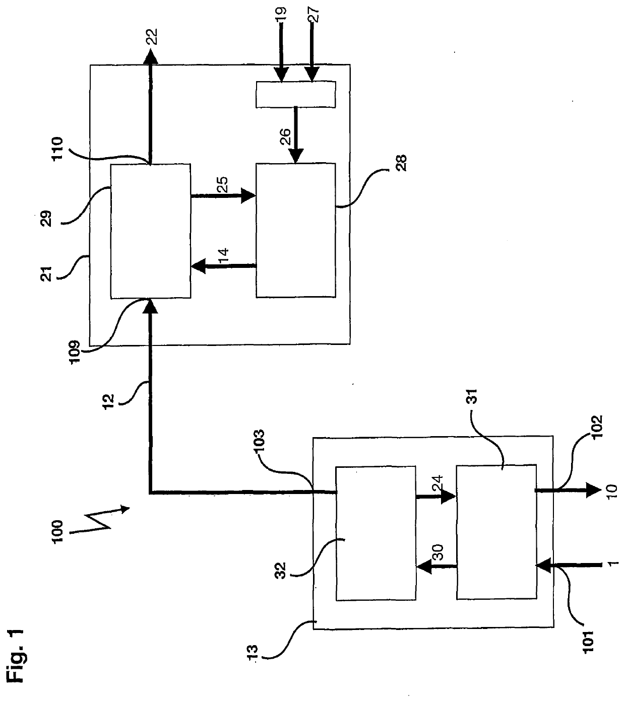
[0020]Referring now to FIG. 1 there is shown the block flow diagram of the invention. The feedstock, or educt 1, which may comprise any organic solid and / or pasty matter or mixtures of solid organic matter and / or liquid organic matter such as wood waste, plastics, organic household waste or tires is being disintegrated under heat and an oxygen deprived atmosphere in a pyrolysis unit 13. Liquid matter may also be educt 1 for some embodiments. The pyrolysis unit 13 may be heated and may operate at a certain elevated temperature, such as from 200-1200 C or more preferably about 600 C (for at least some wood waste as educt 1) to sustain a pyrolysis reaction. Products from the pyrolysis process of the treated educt 1 are: output char 10 and a gas / vapor mixture 12.

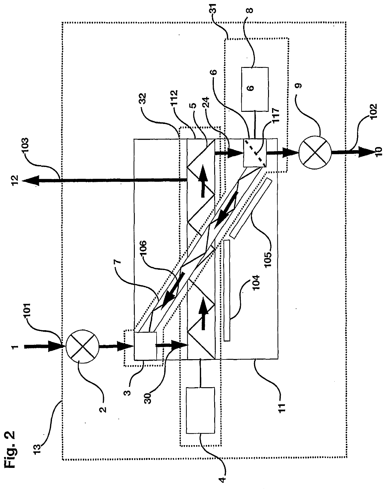
[0021]A first, often a primary, pyrolysis reactor 32 may be fed with a stream 30, which may preferably be a mixture of the educt 1, received at inlet 101, and a portion of hot, recycled char 106 from return auger 31. The recycle...


PUM


Abstract

A syngas generator has at least pyrolysis unit and a cracking unit which recycles treated input therein. The pyrolysis unit may recycle treated char to provide input heat for feedstock. The cracking unit may recycle syngas to assist in treating input gas/vapor mixture.

Description

CLAIM OF PRIORITY[0001]This application claims the benefit of U.S. Provisional Patent Application No. 62 / 788,870 filed Jan. 6, 2019, which is incorporated herein by reference in its entirety.FIELD OF THE INVENTION[0002]An object of the present invention is to potentially provide an efficient and / or compact system to convert organic material contained in organic waste, biomass, and / or other organic materials into a combustible, tar-reduced gas that may be utilized directly in such equipment an internal combustion machine or turbine for the generation of electricity, mechanical energy, and / or for other uses such as use in subsequent synthesis systems such as for the production of biodiesel, etc.BACKGROUND OF THE INVENTION[0003]A device for the pyrolysis and gasification of organic material such as organic household waste, wood waste, tires, plastics, or other hazardous organic components is commonly called a syngas generator. Syngas generators are used to provide a flammable gas / vapor...

Claims


Application Information

Patent Timeline
IPC IPC(8): C10J3/66C10J3/72C10J3/82
CPCC10J2200/15C10J2300/1603C10J2300/0946C10J2200/36C10J2300/1637C10J2300/0916C10J2300/1653C10J3/721C10J3/66C10J3/82C10J2300/1823C10J3/485C10J2300/0956C10J2300/0959C10J2300/0976Y02E20/18Y02P20/145
Inventor NESTLER, HELGE CARL
Owner NESTLER HELGE CARL
Why Eureka
Try Eureka