Acoustic camera systems and methods for large scale flow analysis in turbid field environments

a technology of turbid field environment and camera system, applied in the direction of liquid/fluent solid measurement, fluid speed measurement, instruments, etc., can solve the problems of ineffective turbid environment, ineffective turbid environment measurement techniques, and inability to accurately measure flow in large-scale field environments. , to achieve the effect of improving the effective side lobe, improving the resolution and improving the dynamic range of the acoustic camera imag

Inactive Publication Date: 2020-07-09
UNITED STATES OF AMERICA THE AS REPRESENTED BY THE SEC OF THE ARMY
View PDF9 Cites 1 Cited by
  • Summary
  • Abstract
  • Description
  • Claims
  • Application Information

AI Technical Summary

Benefits of technology

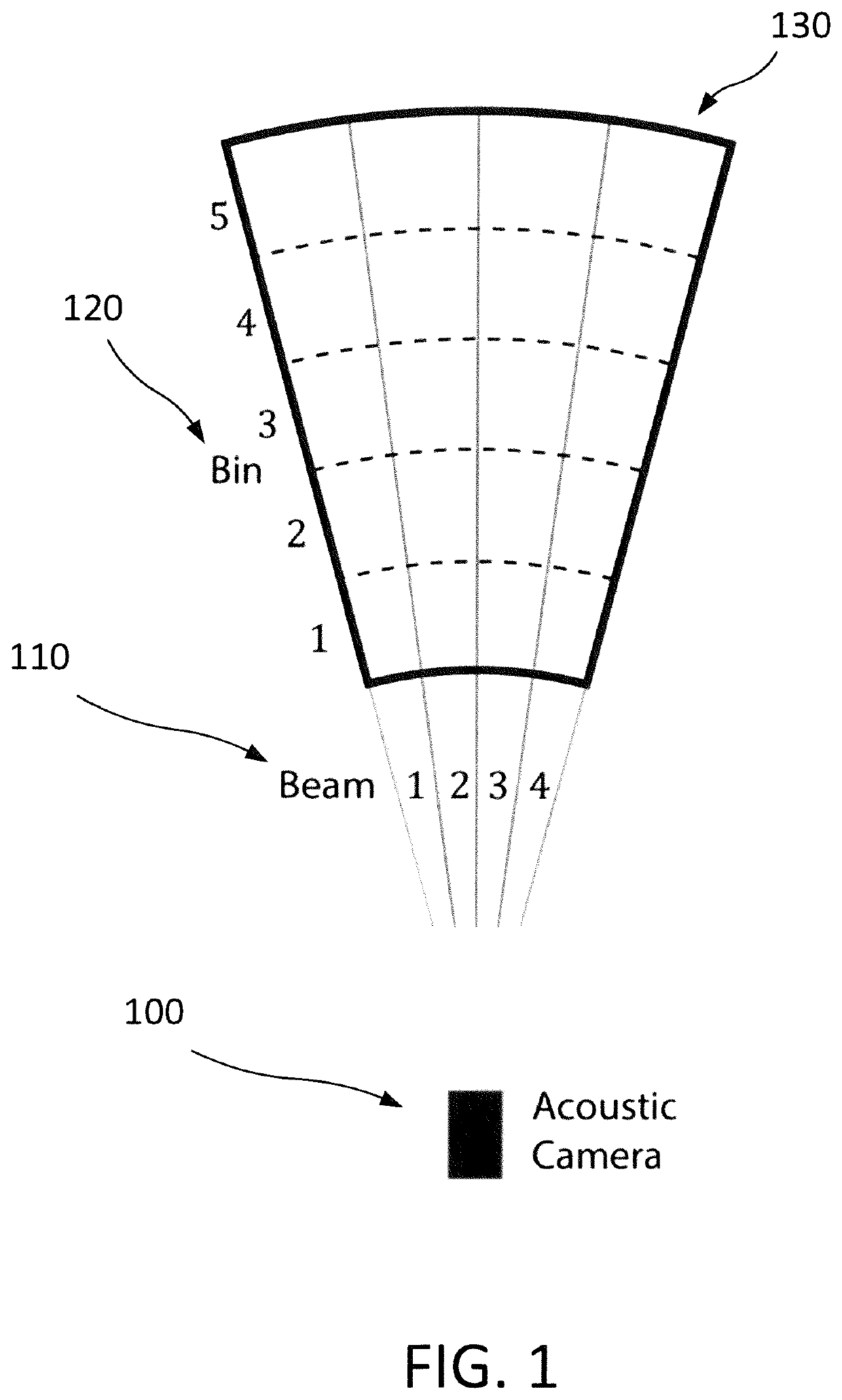
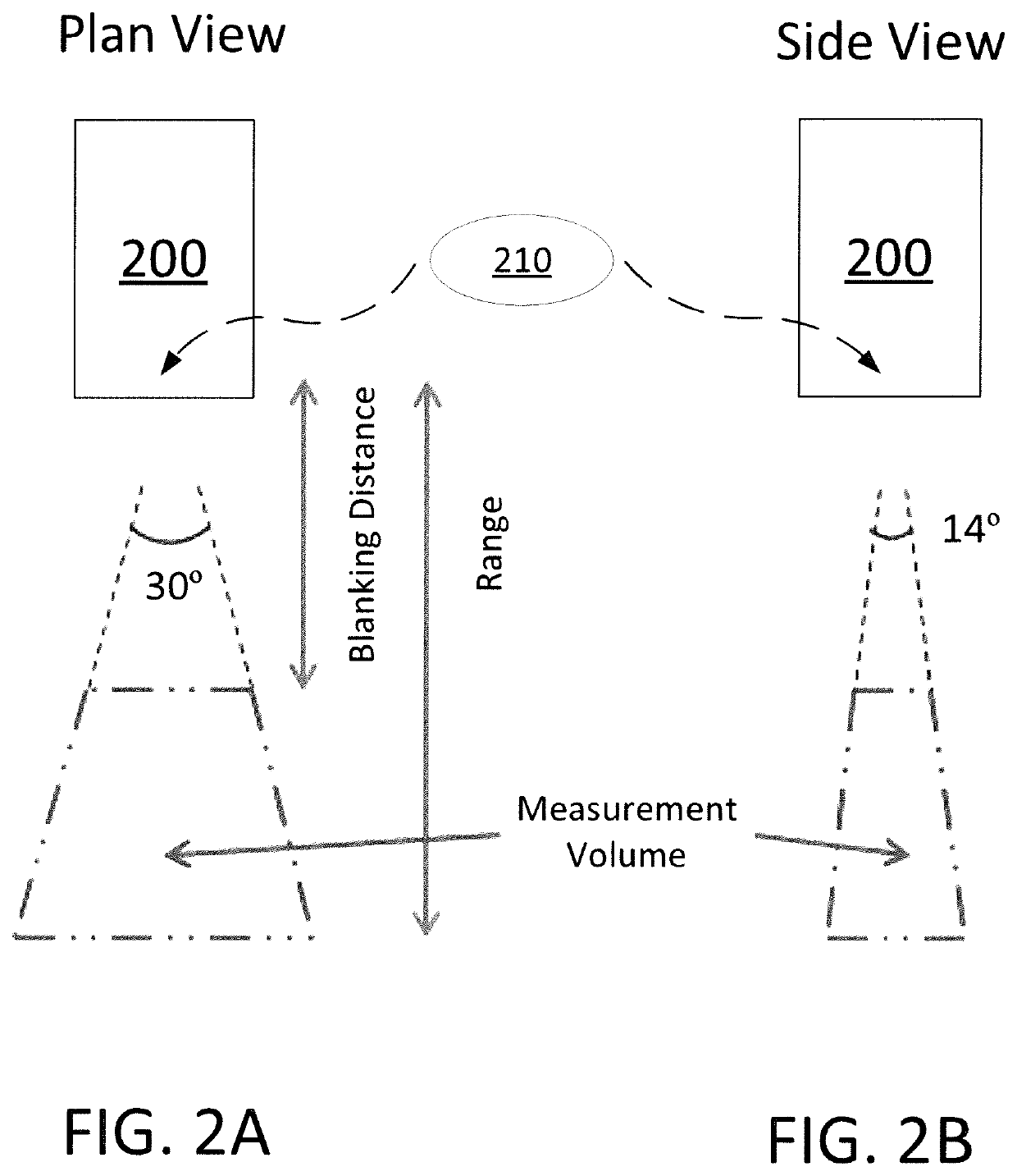
[0023]Acoustic cameras are imaging sonars that provide clear imagery in highly turbid field environments where optical cameras fail. According to some embodiments of the present invention, an acoustic camera is used that forms the acoustic beams solely with acoustic lenses, a significant distinction over the ultrasound imaging devices common in the medical field. The advantage of beamforming with acoustic lenses, rather than the digital transducers used in small field-of-view medical ultrasounds, is that the acoustic lens beamforming is applied to both the transmitted and received signals. This lowers the effective “side lobes” of each individual beam, resulting in better resolution and a higher dynamic range in the acoustic camera images. Furthermore, the acoustic lens approach is more appropriate and effective when imaging larger areas (e.g., 2 m×2 m). Additionally, medical ultrasound systems operate at much higher frequencies than field-deployable acoustic cameras, allowing for much higher resolution over small spatial scales (e.g., mm), but drastically limiting the range of the instrument and thus the scale of the flows measured. Finally, medical ultrasound often employs a contrast agent to deliberately seed the flow (e.g., blood) with scattering particles / bubbles, such as SonoVue 1-10 μm sulfar hexafluoride micro-bubbles. Some embodiments of the present invention do not involve seeding the analyzed flow with any bubbles / particles; rather, the techniques can be applied on the micro-bubbles native to the measured flow field.
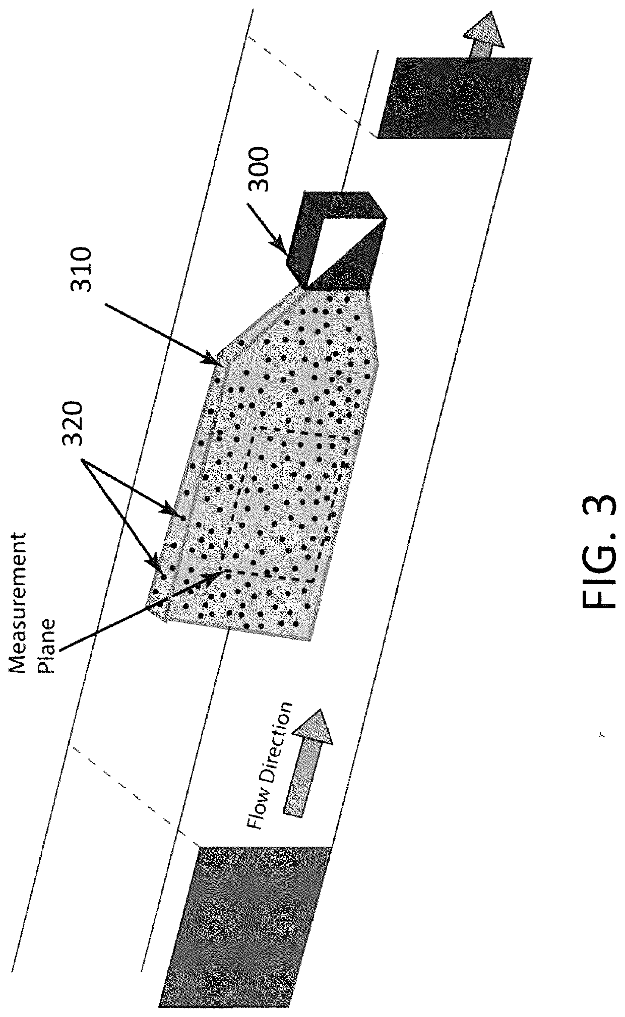
[0024]Hence, embodiments of the present invention encompass techniques that make use of cross-correlation velocimetry to measure flow velocity, and provide a means for extracting velocity information that involves observing and correlating particle / bubble motion from image to image (cross-correlation velocimetry). Advantageously, embodiments of the present invention can be used to effectively obtain two-dimensional velocities in large-scale turbid flows. Moreover, embodiments of the present invention encompass the use of an acoustic imaging device that accomplishes 100% of the beamforming using acoustic lenses to measure a two-dimensional flow field.

Problems solved by technology

Currently available techniques for measuring a plane of two-dimensional flow velocities in a highly turbid environment suffer from significant limitations.
Optical camera-based measurement techniques used to obtain 2D velocity flow fields, such as particle image velocimetry (PIV), are ineffective in turbid environments due to the lack of fluid transparency.
And although certain solutions have been proposed for measuring flow in medical applications, such techniques are not well suited for measuring flow in large scale field environments, such as near dredging operations.
Despite the ubiquity of turbid flows, modern flow measurements lack the capability to acquire velocity vector fields in highly turbid flows.
Traditional particle image velocimetry (PIV) measurement techniques are not well suited to deploy in the field because they are equipment intensive, require stationary well-calibrated images, and often can only be performed in a reasonably transparent fluid (such that the optical camera can see the tracer particles).
Such requirements quickly become restrictive in field deployments, for example in highly turbid environments near dredging operations.
When combined with their high operating frequency, this dramatically limits the scale of the flows such devices are able to adequately image.
And while such techniques may be appropriate for small (mm)-scale medical scenarios, they are not appropriate for large (m)-scale applications such as analyzing flow near dredging operations.
Certain challenges are involved when using PIV-style measurement techniques in the field, as such techniques may require the use of specially-designed apparatuses, for example because PIV with an optical camera is equipment intensive (laser and corresponding optics, camera, image calibration equipment, and the like.
), requires well-calibrated images, and can only be performed in a relatively transparent fluid.
These requirements quickly become restrictive in field deployments, particularly fluid transparency.
Existing acoustic-based flow measurement techniques are capable of making velocity measurements in turbid flows (e.g., acoustic Doppler velocimeters—ADVs—and acoustic Doppler current profilers) but are not able to measure the velocity field in a 2D plane as required to compute spatial velocity gradients and vorticity.
The properties of acoustic waves can make it difficult to perform PIV with traditional seeding particles using an AC.
As a result, particles on the order of 30 μm are difficult to detect with acoustic measurement devices; this is also what makes acoustic measurement techniques effective in turbid water.
Additionally, medical ultrasound systems operate at much higher frequencies than field-deployable acoustic cameras, allowing for much higher resolution over small spatial scales (e.g., mm), but drastically limiting the range of the instrument and thus the scale of the flows measured.

Method used


Image

  • Acoustic camera systems and methods for large scale flow analysis in turbid field environments
  • Acoustic camera systems and methods for large scale flow analysis in turbid field environments
  • Acoustic camera systems and methods for large scale flow analysis in turbid field environments

Examples


Embodiment Construction

[0031]Detailed illustrative embodiments of the present invention are disclosed herein. However, specific structural and functional details disclosed herein are merely representative for purposes of describing example embodiments of the present invention. The present invention may be embodied in many alternate forms and should not be construed as limited to only the embodiments set forth herein. Further, the terminology used herein is for the purpose of describing particular embodiments only and is not intended to be limiting of example embodiments of the invention.

[0032]As used herein, the singular forms “a,”“an,” and “the,” are intended to include the plural forms as well, unless the context clearly indicates otherwise. It further will be understood that the terms “comprises,”“comprising,”“includes,” and / or “including,” specify the presence of stated features, steps, or components, but do not preclude the presence or addition of one or more other features, steps, or components. It ...


PUM


Abstract

In one embodiment, a field-deployable acoustic camera system is provided for measuring a two-dimensional velocity field in a large scale flow in a turbid environment. The system includes an acoustic camera and a concentrator lens. The concentrator lens operates to reduce a spreading angle of the acoustic camera. The system is configured to apply planar cross-correlation velocimetry to collected images of native micro-bubble and/or suspended particle motion collected in turbid environments such as lake circulation, riverine, estuarine, and coastal flows, as well as turbid flows that occur near dredging operations.

Description

STATEMENT OF GOVERNMENT INTEREST[0001]Under paragraph 1(a) of Executive Order 10096, the conditions under which this invention was made entitle the Government of the United States, as represented by the Secretary of the Army, to an undivided interest therein on any patent granted thereon by the United States. This and related patents are available for licensing to qualified licensees.BACKGROUNDField of the Invention[0002]The present invention relates to environmental monitoring techniques, and, more particularly but not exclusively, to the use of field-deployable acoustic camera systems and methods for analyzing turbid flows, for example near dredging operations.Description of the Related Art[0003]This section introduces aspects that may help facilitate a better understanding of the invention. Accordingly, the statements of this section are to be read in this light and are not to be understood as admissions about what is prior art or what is not prior art.[0004]Currently available t...

Claims


Application Information

Patent Timeline
Patent Type & Authority Applications(United States)
IPC IPC(8): G01F1/66G01F1/00
CPCG01F1/002G06F3/147G01F1/662G01P5/241G01P5/001
Inventor MCFALL, BRIAN C.YOUNG, DAVID L.BRYANT, DUNCAN B.WELP, TIMOTHY L.
Owner UNITED STATES OF AMERICA THE AS REPRESENTED BY THE SEC OF THE ARMY
Why Eureka
Try Eureka