In-vehicle network anomaly detection system and in-vehicle network anomaly detection method

a technology of vehicle network and detection system, which is applied in the direction of failsafe aspects, data switching networks, electric devices, etc., can solve the problems of unauthorized access from an external network, difficult to fully make a transition, and communication speed restriction

Active Publication Date: 2020-07-09
PANASONIC INTELLECTUAL PROPERTY CORP OF AMERICA
View PDF0 Cites 8 Cited by
  • Summary
  • Abstract
  • Description
  • Claims
  • Application Information

AI Technical Summary

Benefits of technology

[0016]The in-vehicle network anomaly detection system and the in-vehicle network anomaly detection method of the pre

Problems solved by technology

A communication data amount on an in-vehicle network increases with the number of ECUs and thus results in a restriction at the communication speed of CAN.
It is currently difficult to fully make a transition from CAN to Ethernet in

Method used


Image

  • In-vehicle network anomaly detection system and in-vehicle network anomaly detection method
  • In-vehicle network anomaly detection system and in-vehicle network anomaly detection method
  • In-vehicle network anomaly detection system and in-vehicle network anomaly detection method

Examples


embodiment

[System Configuration]

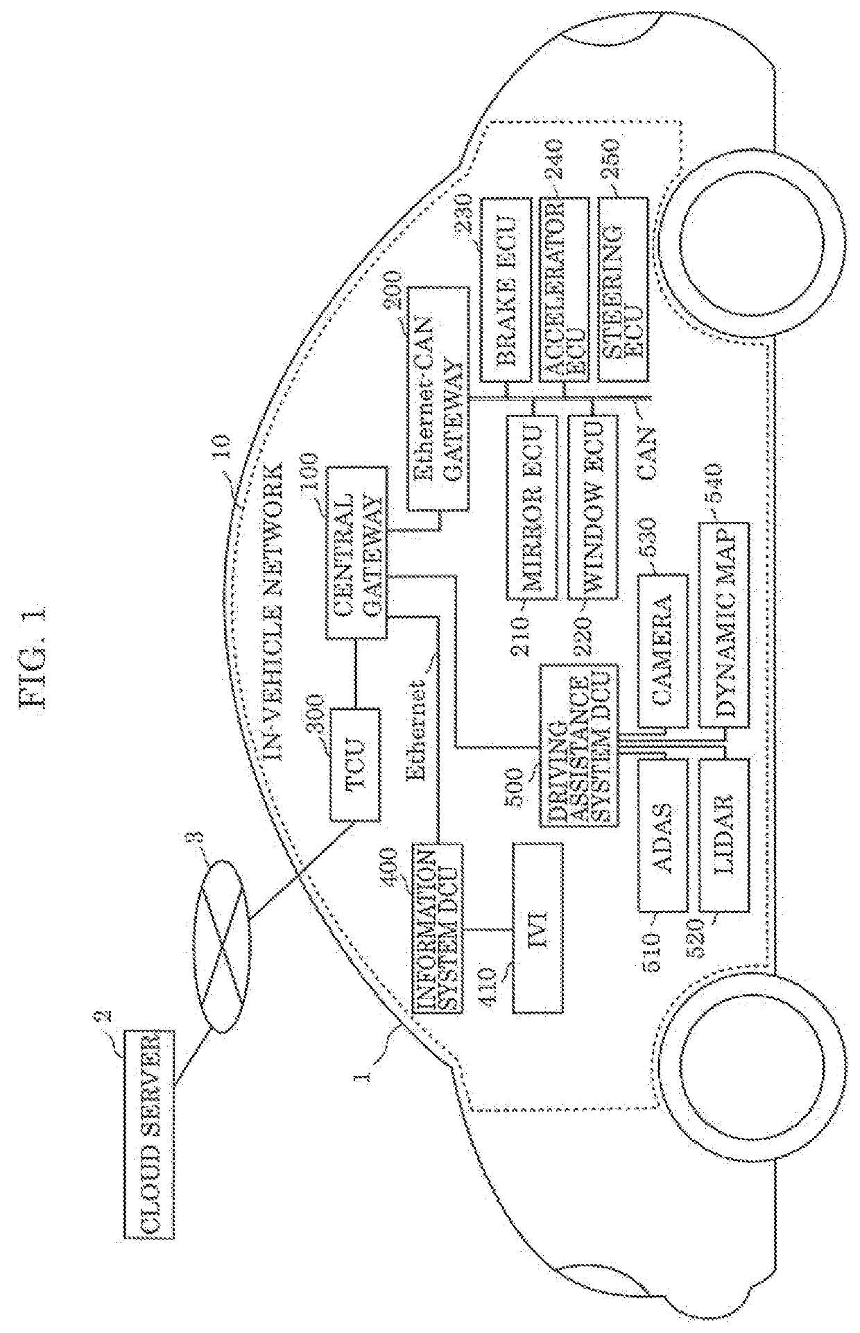
[0054]FIG. 1 is an overall block diagram of an in-vehicle network according to an embodiment. In-vehicle network 10 installed in vehicle 1 includes a network that is constructed according to an Ethernet protocol and is illustrated by a single solid line and a network that is in compliance with a CAN protocol and is illustrated by a double solid line. In the present embodiment, the Ethernet protocol is an example of a first protocol and the CAN protocol is an example of a second protocol.

[0055]Central gateway 100 included in in-vehicle network 10 is connected to Ethernet-CAN gateway 200, telematics control unit (hereinafter, will be referred to as a TCU) 300, information system Domain Control Unit (DCU) 400, and driving assistance system DCU 500 via Ethernet communication lines.

[0056]TCU 300 included in in-vehicle network 10 is a unit for communications of vehicle 1 with cloud server 2 via external network 3. In the present embodiment, for example, TCU 300 is a ...


PUM


Abstract

An anomaly detection system is on an in-vehicle network including: a first network connected to first devices that communicate using a first protocol; and a second network connected to second devices that includes a driving assistance controller communicates using a second protocol. The system includes: a communicator receiving, through the first network, first unit data including (i) source information indicating a source first device and (ii) second unit data including a data identifier; a database storing rule; and an anomaly determiner that determines whether the first unit data has anomaly by comparing the source information and the data identifier with the rule. Based on the rule, the first unit data is determined to have anomaly when the source first device is a sensing device and, according to the identifier, the second unit data is to be received by the controller.

Description

CROSS REFERENCE TO RELATED APPLICATIONS[0001]This application is a U.S. continuation application of PCT International Patent Application Number PCT / JP2018 / 045619 filed on Dec. 12, 2018, claiming the benefit of priority of Japanese Patent Application Number 2017-240759 filed on Dec. 15, 2017, the entire contents of which are hereby incorporated by reference.BACKGROUND1. Technical Field[0002]The present disclosure relates to detection of an anomaly of an unauthorized message from among messages used on an in-vehicle network.2. Description of the Related Art[0003]In recent years, a system included in an automobile has a large number of devices called electronic control units (hereinafter, referred to as ECUs). Such a network connecting the ECUs is called an in-vehicle network. Among many standards established for in-vehicle networks, Controller Area Network (hereinafter, referred to as CAN (registered trademark)) with a maximum communication speed of about 1 Mbps is generally used.[000...

Claims


Application Information

Patent Timeline
IPC IPC(8): H04L29/06H04L12/40H04L29/08B60R16/023B62D5/04B60T17/22B60L3/00
CPCH04L67/12B60T17/221B60L3/0023B60R16/023B62D5/0481H04L63/1425H04L2012/40215H04L2012/40273H04L12/40B60T2270/40B60T7/18B60T8/88B60T8/885B60T2270/406B60L3/0084B60L2240/24B60L2250/26H04L12/40169H04L12/4625H04W4/48H04W4/024Y02T90/16
Inventor TERAZAWA, HIROYASUHAGA, TOMOYUKITORISAKI, YUISHIKATO, RYO
Owner PANASONIC INTELLECTUAL PROPERTY CORP OF AMERICA
Why Eureka
Try Eureka