Separation device

a technology of separation device and sieve, which is applied in the direction of separation process, filtration separation, papermaking, etc., can solve the problems that the prior art device is not good for this kind of separation, and achieve the effect of reducing the tendency of the disc, thus energy consumption, and reducing the flow resistance through the siev

Active Publication Date: 2020-07-16
ANDRIZ OY
View PDF0 Cites 1 Cited by
  • Summary
  • Abstract
  • Description
  • Claims
  • Application Information

AI Technical Summary

Benefits of technology

[0009]Advantageously the angle between the outer surface of the disc or the front edges of the protrusions of the disc and the front surfaces of the sieves is positive and most preferably over 10 degrees, whereby the protrusion pushes to its outer circumference and towards the reject conduit a piece stopped by the sieve. A gently rising front surface, where the angle between the sieve is large, also decreases the tendency of the discs to cause swirling and fluidizing flow around them. Flow resistance and thus energy consumption can be further decreased by shaping the front surface of at least some protrusions convex and/or back surface tapered. Advantageously at least some of the teeth of the sieves are at their apex in the thickness direction chamfered thinner than at their base, whereby the flow resistance through the sieve is minimized, but the construction remains solid. Especially the front surface of the first sieve can be convex. The front surface of the sieve means the surface facing the direction of rotation of the discs. Still more advantageously the trailing edge of the first sieve is tapered, i.e. the shaping of the teeth of the sieve can correspond to the shaping of the protrusion of the disc that was mentioned earlier. The front surfaces and trailing edges of the second sieve are advantageously shaped in an opposite way, because the flow direction of the pulp is to the other direction. Decreasing the flow resistances balances the flows between the first and the second sieve. Also the risk of accumulation of blockage by fibers and passed through pieces behind the second sieve is decreased. Then the sieve can be located closer to the feed conduit. When the outer surface of the disc is substantially round, i.e. without protrusions or with low protrusions, the angle between the front surface of the sieve and the outer surface of the disc is advantageously over 80 degrees. Then oversize pieces are guided outwardly and do not get stuck between the disc and the sieve.
[0010]Advantageously the second sieve is beside the accept conduit in the direction of rotation of the shaft downstream of the accept conduit. Then rotation of discs does not cause substantial backflow, but the sieve guides pulp into the accept conduit. On the other hand, it may be advantageous to locate the second sieve beside the feed conduit, whereby especially heavy metallic reject pieces fall more efficiently down towards the reject conduit and fiber-containing lighter materials more efficiently move along into the first ...

Problems solved by technology

Prior art devices are not ...

Method used


Image

  • Separation device
  • Separation device
  • Separation device

Examples


Embodiment Construction

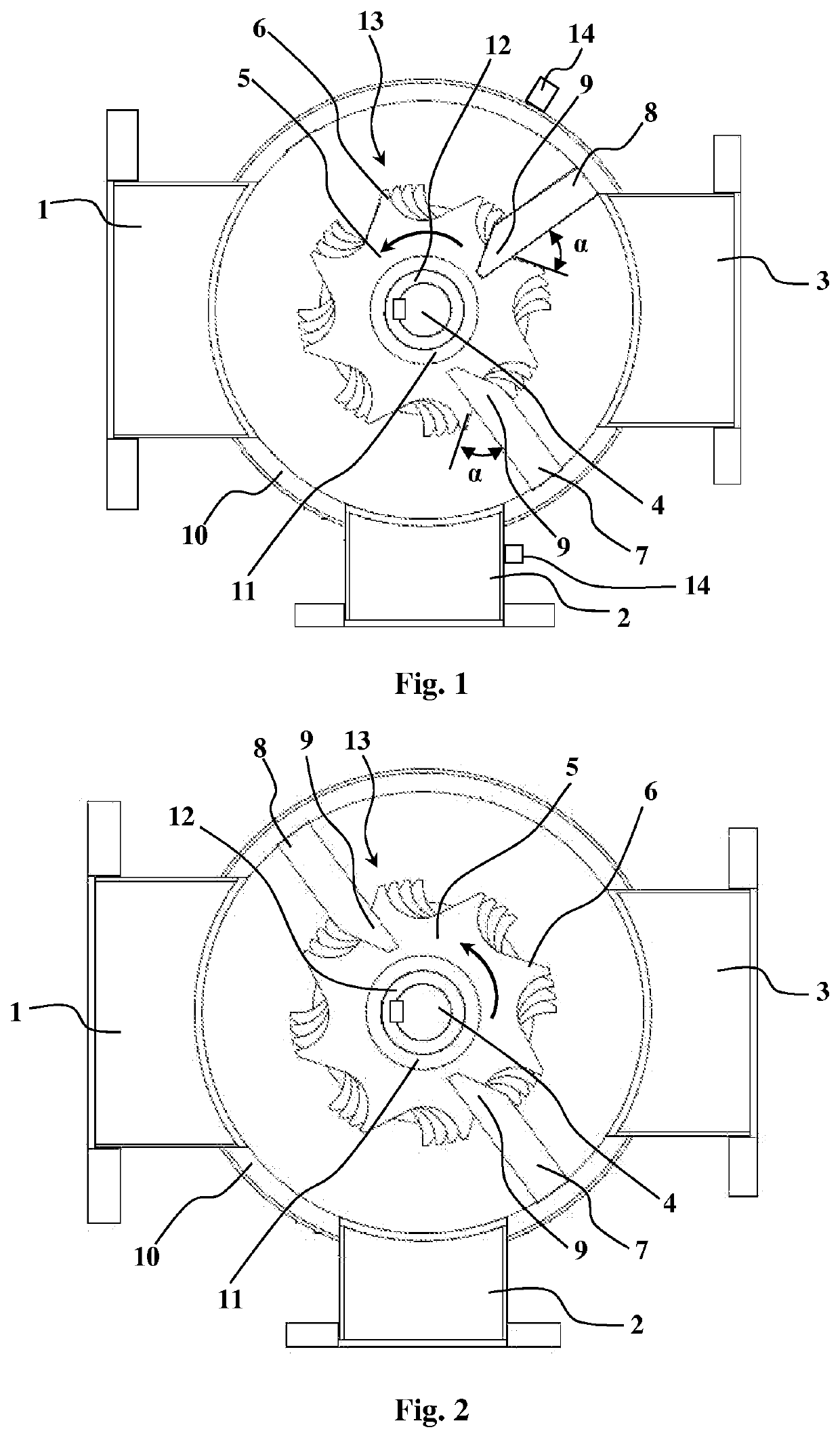
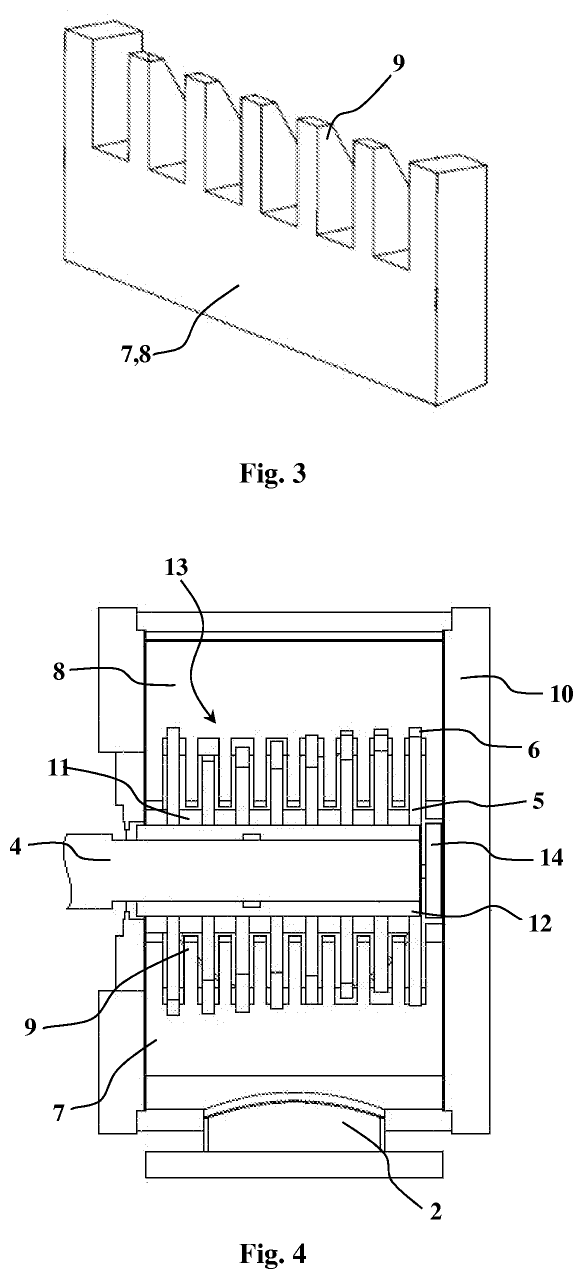
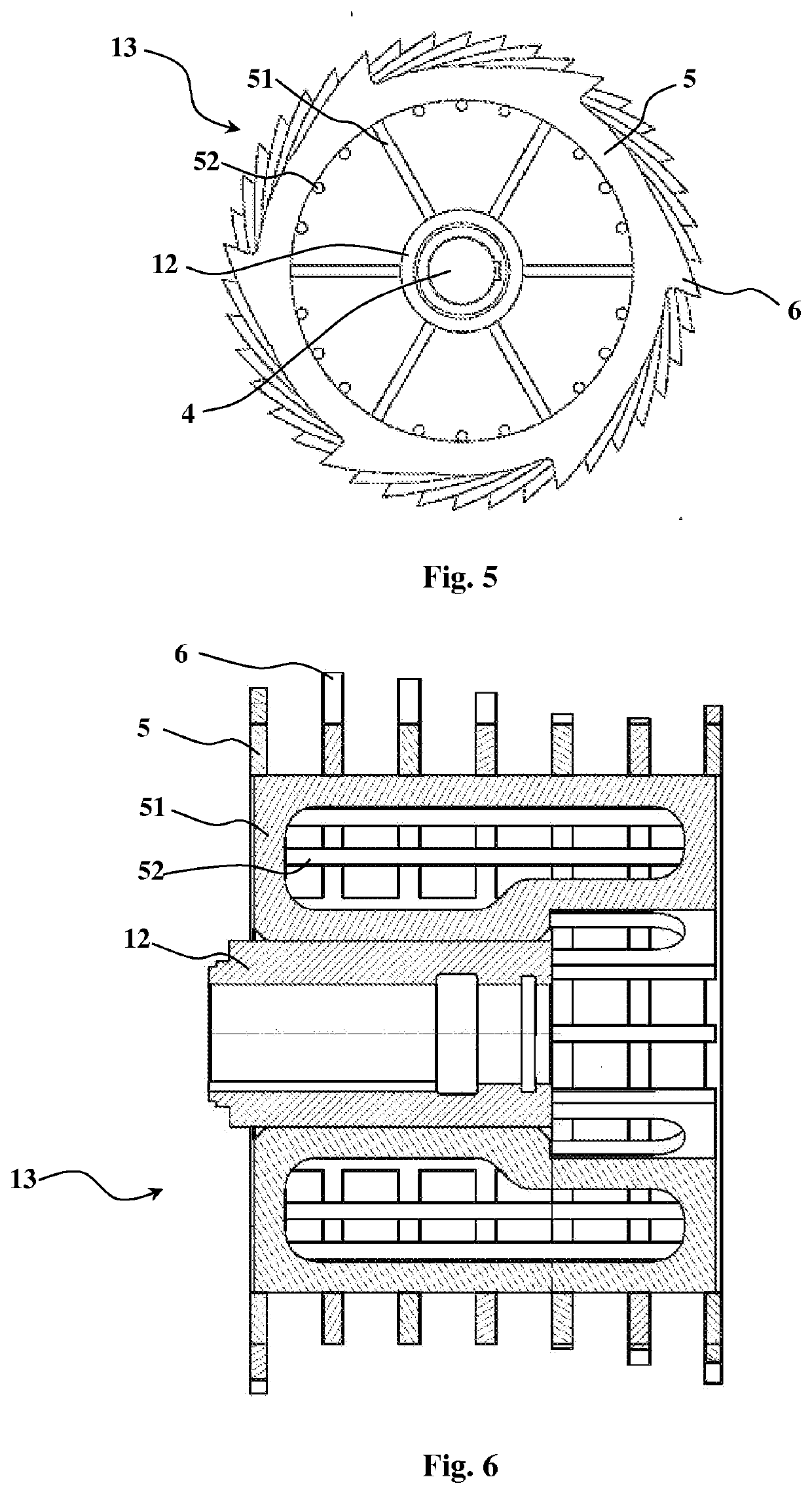
[0025]FIG. 1 illustrates a preferred embodiment of the separation device having a housing 10 with a feed conduit 1 and a reject conduit 2, between which conduits 1 and 2 and an accept conduit 3 a rotor unit 13 is arranged. The rotor unit 13 has a shaft 4 transverse with respect to the through-flow direction, which shaft 4 rotates discs 5 attached to the shaft 4, and at least two sieves 7 and 8. The shaft 4 is advantageously in horizontal position. The outer surface of the discs 5 is provided with protrusions 6. Between the discs 5 there may be support sleeves 11, which keep their distances equal. More advantageous direction of rotation is marked in the Figure. The rotational speed of the discs 5 is advantageously between 200-1000 rpm. Advantageously at least some protrusions 6 of different discs 5 are at various locations in the rotational direction of the shaft 4. Advantageously the shaft is provided with a tube shaft 12, onto which the discs 5 and optional support sleeves 11 are a...


PUM

PropertyMeasurementUnit
Angleaaaaaaaaaa
Shapeaaaaaaaaaa
Distanceaaaaaaaaaa

Abstract

A separation device having a housing (10) with a feed conduit (1) and a reject conduit (2), between which conduits (1, 2) and an accept conduit (3) of the housing (10) is a rotor unit (13) having a shaft (4) transverse to the through-flow direction of the separation device, which shaft rotates discs (5) attached to the shaft (4), the outer surface and/or side surfaces of which discs are jagged, i.e. they have protrusions (6) and/or notches and/or these surfaces are substantially rough and the teeth (9) of at least two sieves (7, 8) attached to the housing (10), extend between the discs (5), the first sieve (7) being between the reject conduit (2) and the accept conduit (3) and the second sieve (8) being between the feed conduit (1) and the accept conduit (3).

Description

[0001]The invention relates to a separation device for separating oversize pieces from liquid and solids containing suspension, such as cellulose suspension. More precisely, the invention relates to a separation device according to claim 1.BACKGROUND OF THE INVENTION[0002]The equipment and processes of the cellulose and paper industry usually endure some amount of different impurities, such as sand, but the feed material may contain larger pieces such as stones, bolts etc. metal pieces. Fibrous pieces can often be utilized and defibrated in later process stages, as long as they do not hamper the operation of the equipment. The aim is to keep the feed pulp at a high concentration, due to which it contains pieces, which at a lower concentration would remain on the bottom of the basins and containers. Usually a largest particle size is determined for process equipment, which the equipment endures without being damaged or without compromising quality. The purpose of the separation devic...

Claims


Application Information

Patent Timeline
IPC IPC(8): B07B13/00D21D5/06
CPCB07B2230/01D21D5/06B07B13/003D21B1/026D21D5/20B01D29/00B01D29/64D21D5/00
Inventor PELTONEN, KARIVEHMAA, JANNEKAIPAINEN, VESASIIK, SAMIPORKKA, SAMPSA
Owner ANDRIZ OY
Why Eureka
Try Eureka