
Color Sorting Machine

a sorting machine and color technology, applied in the direction of sorting, etc., can solve the problems of foreign matter that cannot be properly removed, unstable airflow, foreign matter, etc., and achieve the effect of removing foreign matter properly and specific gravity

Active Publication Date: 2020-07-16
HATTORI SEISAKUSHO
View PDF0 Cites 2 Cited by
  • Summary
  • Abstract
  • Description
  • Claims
  • Application Information

AI Technical Summary

Benefits of technology

The present invention provides a color sorting machine that can effectively remove even low-spec objects. It does this by using a suction device to generate an airflow that removes foreign matter and stabilizes the object's movement through the sorting region. This ensures that the removal device can easily detect and remove any foreign matter, resulting in a high-quality final product.

Problems solved by technology

As a result, in some cases, the compressed air does not hit the detected foreign matter, with the result that the foreign matter cannot be properly removed.
That is, in the sorting region, the airflow is unstable.
As a result, in the case where the specific gravity of the object to be sorted 200 is lower than that supposed by this color sorting machine, the object to be sorted 200 is dispersed in all directions when it has passed between the transparent walls 800a and 800b. As a result, the compressed air may not hit the detected foreign matter and the foreign matter may not be properly removed.

Method used


Image

  • Color Sorting Machine
  • Color Sorting Machine
  • Color Sorting Machine

Examples


first embodiment

[0026]The first embodiment of the present invention will be described with reference to the accompanying drawings.

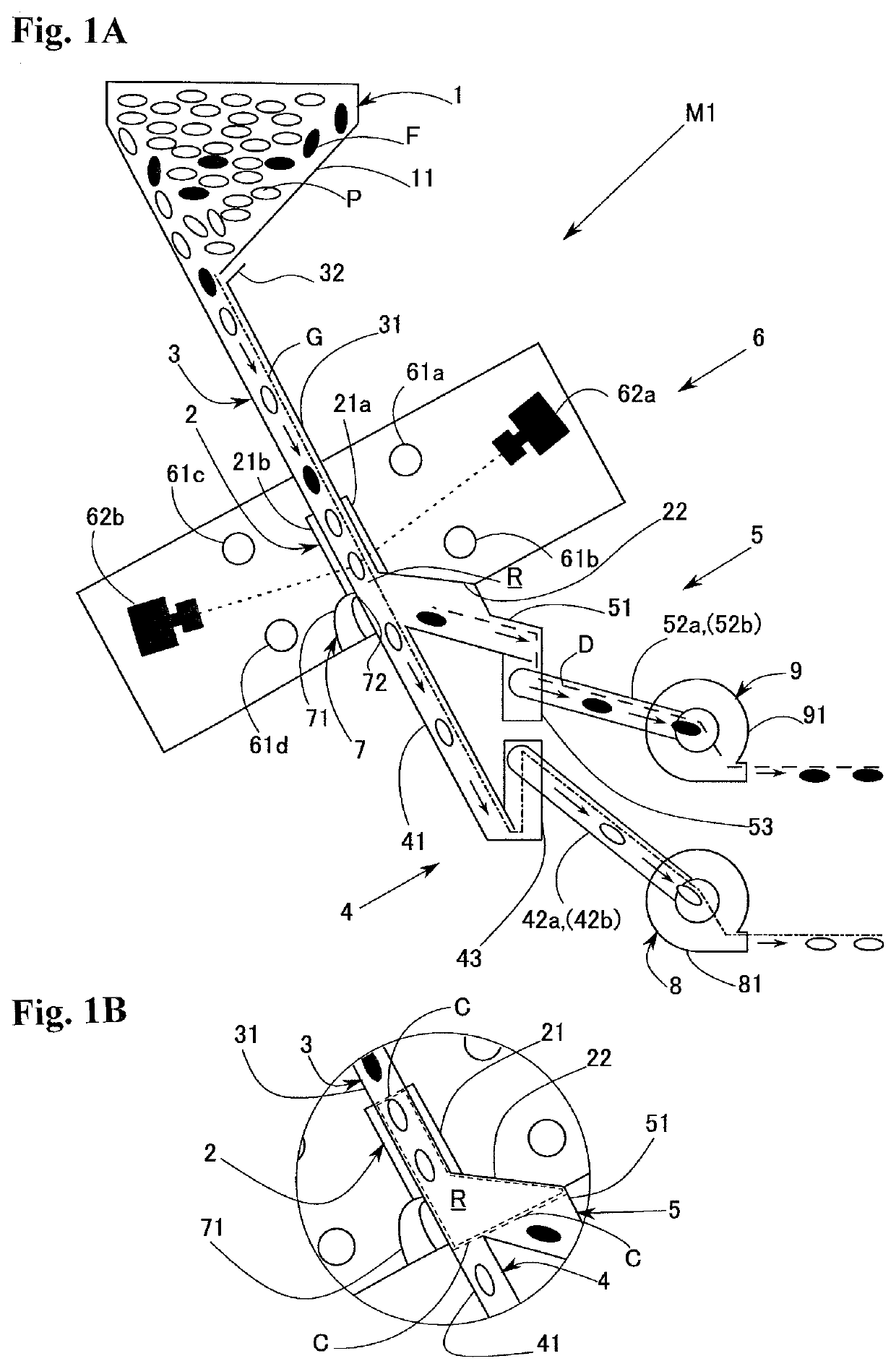
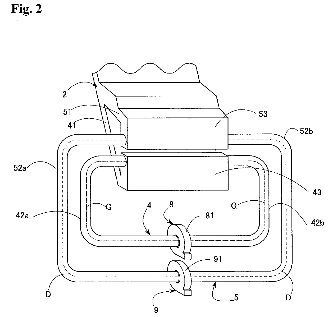
[0027]FIG. 1A is a schematic sectional view of a color sorting machine M1 according to the first embodiment of the present invention. The color sorting machine M1 is equipped with a supply portion 1, a sorting portion 2, a first conveying portion 3, a second conveying portion 4, a removing portion 5, a detection device 6, a removal device 7, a first suction device 8, and a second suction device 9. The color sorting machine M1 conveys an object to be sorted along a conveyance route G, and while doing so, removes in a sorting region R a predetermined object in the object to be sorted as foreign matter F into a removal route D extending from the sorting region. R.

[0028]The supply portion 1 temporarily stores the object to be sorted, and supplies the object to be sorted to the conveyance route G. The supply portion 1 has a hopper 11, and the object to be sorted flows out of ...

second embodiment

[0059]Subsequently, the second embodiment of the present invention will be described.

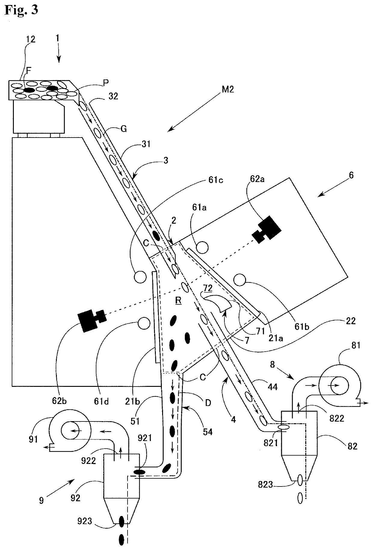
[0060]FIG. 3 is a schematic sectional view of a color sorting machine M2 according to the second embodiment of the present invention. The components that are the same as those of the above-described embodiment are indicated by the same reference numerals, and a detailed description thereof will be left out.

[0061]The supply portion 1 has a vibration feeder 12 instead of the hopper 11. The vibration feeder 12 vibrates, whereby the object to be sorted flows out of the vibration feeder 12 into the conveyance route G.

[0062]In the sorting portion 2, the transparent walls 21a and 21b are provided so as to be sufficiently spaced away from the conveyance route G.

[0063]The air intake port 32 is provided at the upstream end of the chute 31. The object to be sorted flows out of the vibration feeder 12 into the conveyance route G via the air intake port 32.

[0064]Instead of the upstream conveying portion 41 and t...

third embodiment

[0073]Subsequently, the third embodiment of the present invention will be described.

[0074]FIG. 4A is a schematic sectional view of a color sorting machine M3 according to the third embodiment of the present invention. The components that are the same as those of the above-described embodiments are indicated by the same reference numerals, and a detailed description thereof will be left out.

[0075]As shown in FIGS. 4A and 4B, instead of the removal device 7, the color sorting machine M3 is equipped with a route switching device 10. When no foreign matter F is detected, the route switching device 10 establishes communication between the sorting portion 2 and the second conveying portion 4, and prohibits communication between the sorting portion 2 and the removing portion 5. When some foreign matter F is detected, the route switching device 10 prohibits communication between the sorting portion 2 and the second conveying portion 4, and establishes communication between the sorting porti...


PUM


Abstract

Provided is a color sorting machine capable of properly removing foreign mater even when the specific gravity of the object to be sorted is low. A color sorting machine MI removes foreign matter F in the object to be sorted being conveyed from a conveyance route G into a removal route R. The color sorting machine M1 is equipped with a supply portion 1 supplying the object to be sorted to the conveyance route G, a sorting portion 2 surrounding a sorting region R and partially formed by transparent walls 21a and 21b, a first conveying portion 3 surrounding the periphery of the conveyance route G to the sorting region R, a second conveying portion 4 hermetically surrounding the periphery of the conveyance route G from the sorting region R, a removing portion 5 hermetically surrounding the periphery of the removal route D extending from the sorting region R, an air intake port 32, a detection device 6 optically detecting the foreign matter F in the object to be sorted, a removal device 7 having an ejection port 72 hermetically inserted into the sorting portion 2, and a first suction device 8 provided in the second conveying portion 4 and sucking in the air in the conveyance route G to thereby generating an airflow heading for the second conveying portion 4 from the air intake port 32.

Description

TECHNICAL FIELD OF THE INVENTION[0001]The present invention relates to a color sorting machine for removing foreign matter in an object to be sorted.BACKGROUND OF THE INVENTION[0002]Conventionally, there has been known a color sorting machine removing foreign matter in an object to be sorted such as grain (See, for example, Patent Document 1). In this type of color sorting machine, an object to be sorted first flows down on a chute to be released into a sorting region. Next, a detection device applies light to the object to be sorted passing through the sorting region and takes a picture of the object to be sorted to produce an image, and detects foreign matter based on the image. When foreign matter is detected, a removing device ejects compressed air against the detected foreign matter to remove the foreign matter.[0003]An object to be sorted of low specific gravity such as flour, however, does not pass through the sorting region at a fixed speed and on a fixed track due to the ai...

Claims


Application Information

Patent Timeline
IPC IPC(8): B07C5/342B07C5/36
CPCB07C5/363B07C5/3422B07C5/361B07C5/342
Inventor HATTORI, KATSUHIRO
Owner HATTORI SEISAKUSHO
Learn More