Roof window system with improved transition means between a roof window and a ventilation assembly

a technology of roof windows and ventilation assemblies, applied in ventilation systems, lighting and heating apparatus, heating types, etc., can solve the problems of severe limitations in retrofitting existing windows, and still exist retrofit challenges, so as to improve environmental conditions, improve connection, and increase insulation

Active Publication Date: 2020-07-16
VKR HLDG AS
View PDF0 Cites 2 Cited by
  • Summary
  • Abstract
  • Description
  • Claims
  • Application Information

AI Technical Summary

Benefits of technology

[0008]With this background, it is therefore an object of the present invention to provide a roof window system, which provides for an improved connection between the roof window and the ventilation assembly, irrespective of the functionality of the roof window, and which at the same time provides for increased insulation and overall improved environmental conditions.
[0010]Thereby a roof window system is provided in which the transition between the two components of the roof window system, i.e. the roof window and the ventilation assembly, is carried out at a position which is as neutral as possible, that is, rather than leading the flow paths above the top frame member as in the prior art, the frame may accommodate other equipment as well, for instance a top hinge device. Furthermore, guiding the air through the frame top member also entails improved insulation properties, as the flow paths will extend through an area with better insulation.

Problems solved by technology

Thus, severe limitations as to retro-fitting existing windows exist.
Furthermore, challenges as to retrofitting still exist, since the construction of the relevant parts of the roof window depends on the functionality.

Method used


Image

  • Roof window system with improved transition means between a roof window and a ventilation assembly
  • Roof window system with improved transition means between a roof window and a ventilation assembly
  • Roof window system with improved transition means between a roof window and a ventilation assembly

Examples


Embodiment Construction

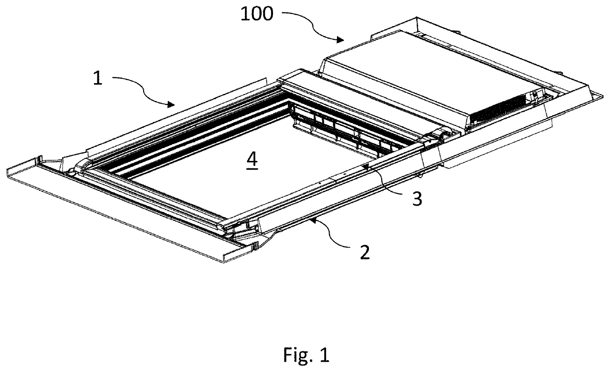
[0030]Referring first to FIG. 1 showing the overall appearance and principles underlying a roof window system in an embodiment of the invention, the roof window system comprises a roof window 1 and a ventilation assembly generally designated 100.

[0031]The roof window 1 comprises at least one frame, in the embodiment shown and described two frames, of which one frame 2 is a stationary frame and an openable sash 3 encasing a pane 4. Details of the frame 2 and sash 3 are shown in more detail in i.a. FIGS. 13, 14 and 19. The frame 2 is, in a manner known per se, substantially rectangular and has a top member 21, and further a bottom member 22, and two side members, not shown in detail. The sash 3 has a top member 31 and two side members 32, 33, and further a bottom member, not shown in detail.

[0032]The frame 2 is adapted to be built into a roof structure of virtually any kind, typically comprising a number of rafters and battens, and further non-shown details such as vapour barrier coll...


PUM


Abstract

In a roof window system, the roof window (1) has a frame with a frame top member (21), and a sash with a sash top member (31), and further a ventilation device (40) for connection to a ventilation assembly by means of transition means provided between the ventilation assembly and the frame top member (21) and the sash top member (31) of the roof window (1) to accommodate a set of flow paths for air to and from the ventilation assembly. The transition means comprise a plurality of apertures (2102) extending through the frame top member (21).

Description

TECHNICAL FIELD[0001]The present invention relates to a roof window system comprising a roof window having a frame including a frame top member, two side members and a bottom member, defining a frame plane, and a sash including a sash top member, sash side members and a bottom member, and a pane, the roof window further comprising a ventilation device adapted for providing ventilation of a building in which the roof window is mounted, a ventilation assembly including a housing accommodating at least one ventilation unit connected to an aperture for air intake and exhaust, transition means being provided between the ventilation assembly and the frame top member and the sash top member of the roof window to accommodate a set of flow paths for air to and from the ventilation assembly.BACKGROUND ART[0002]In recent years, the interest in energy-balanced buildings has increased and several attempts have been made to provide houses in which the energy for heating, cooling, water for domest...

Claims


Application Information

Patent Timeline
Patent Type & Authority Applications(United States)
IPC IPC(8): E04D13/035E04D13/03
CPCE04D13/0325E05Y2900/152E06B7/10F24F13/18F24F2221/20E04D13/0354E04D13/031E04D13/03E06B7/02F24F13/28F24F7/013
Inventor JACOBSEN, PERBORUP-JENSEN, RENÉ
Owner VKR HLDG AS
Why Eureka
Try Eureka