Clutch device for compressor

a technology of clutches and compressors, which is applied in the direction of mechanical actuated clutches, couplings, hoisting equipments, etc., can solve the problems that the front plate may have a good chance of disassembly from the drive shaft, and achieve the effect of improving and simplifying the structure or configuration

Active Publication Date: 2020-07-16
CHU HENRY C
View PDF1 Cites 0 Cited by
  • Summary
  • Abstract
  • Description
  • Claims
  • Application Information

AI Technical Summary

Benefits of technology

[0008]The primary objective of the present invention is to provide a clutch device for compressor including an improved and simplified structure or configuration for suitably and solidly and stably anchoring or retaining or securing the front plate and the pulley to the compressor drive shaft and for preventing the front plate from being disengaged or separated from the pulley and the compressor drive shaft inadvertently.
[0012]The lock device includes at least one fastener engaged with the lock member and the front plate for solidly member to the front plate and for preventing the lock member from being rotated relative to the front plate and for preventing the lock member from being disengaged from the front plate inadvertently.

Problems solved by technology

However, the front plate may be solidly anchored or retained or secured to the drive shaft when the pulley is rotated or driven by the belt in an active direction, but the front plate may have a good chance to be disengaged from the drive shaft inadvertently when the pulley is rotated or driven by the belt in an opposite direction,

Method used


Image

  • Clutch device for compressor
  • Clutch device for compressor
  • Clutch device for compressor

Examples


Embodiment Construction

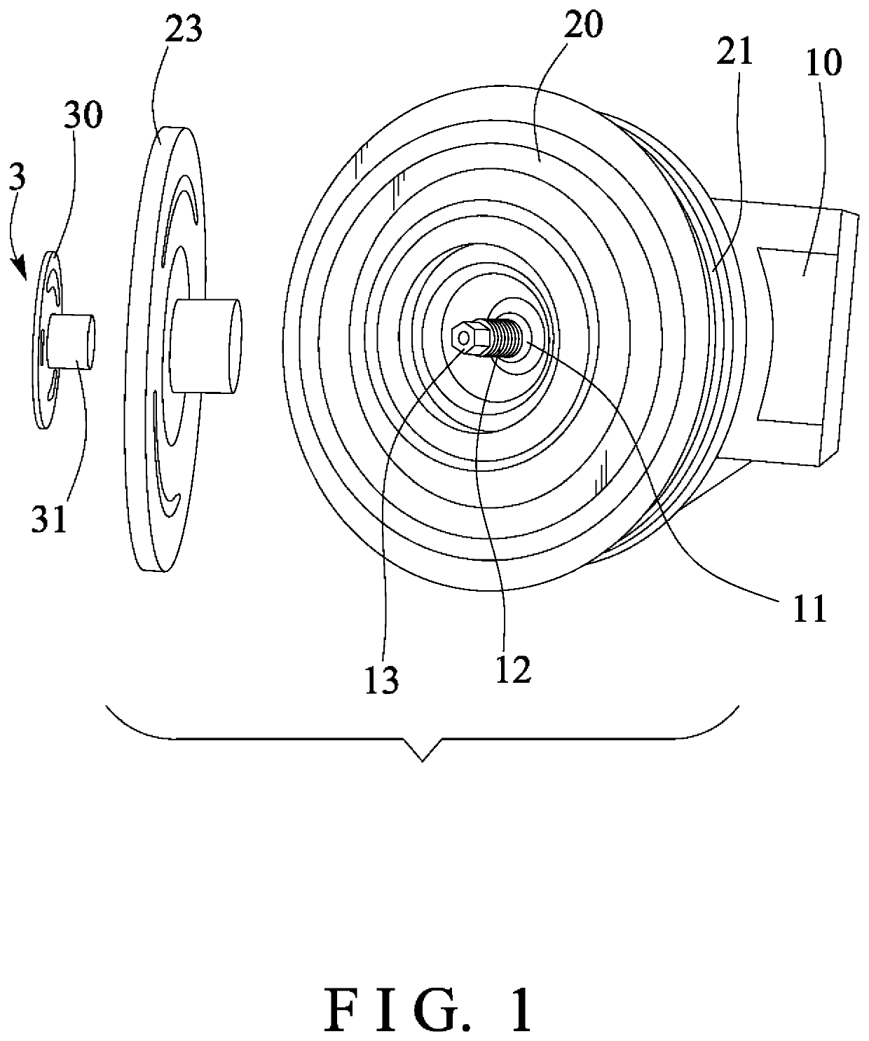
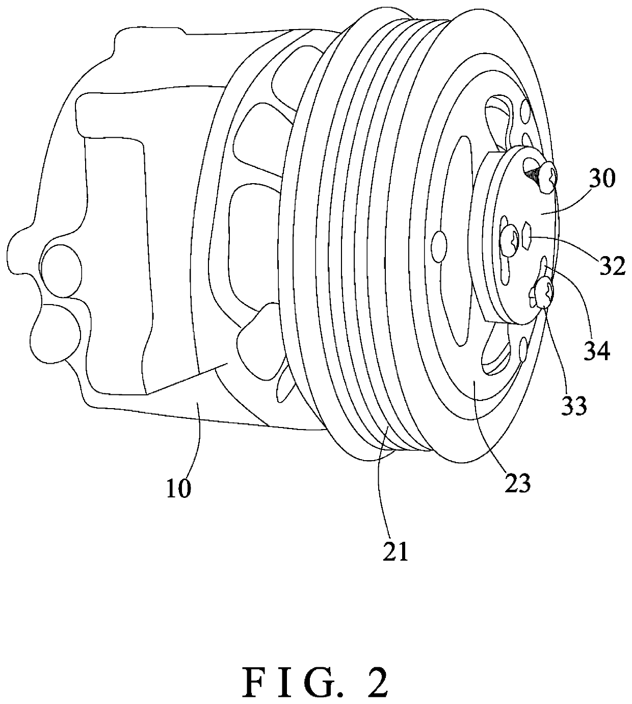
[0022]Referring to the drawings, and initially to FIGS. 1 and 2, a compressor in accordance with the present invention comprises an outer receptacle or housing 10, and a compressor drive shaft 11 rotatably received or engaged in the housing 10, and the drive shaft 11 includes a threaded segment or section 12 and a non-circular segment or section 13 having such as a hexagonal or other cross section (FIG. 1) formed and provided on the outer or free end portion of the drive shaft 11. A coil or stator 20 is attached or mounted or secured to the housing 10, and a pulley 21 is rotatably attached or mounted or secured to the housing 10, such as rotatably engaged onto the stator 20 and rotatable relative to the stator 20 and the housing 10. A pressure plate or front plate 23 includes a threaded hole or screw hole 24 formed or provided therein (FIG. 4) for threading or engaging with the threaded section 12 of the drive shaft 11 and for allowing the front plate 23 to be detachably or changeab...


PUM


Abstract

A compressor includes a housing, a drive shaft rotatably engaged in the housing, a stator attached to the housing, a pulley rotatably attached to the housing and rotatable relative to the housing, a front plate attached to the drive shaft and rotated in concert with the drive shaft, and a lock device includes a lock member attached to the drive shaft and rotated in concert with the drive shaft, and the lock member is secured to the front plate for anchoring and securing the front plate and the lock member and the drive shaft together. The drive shaft includes a non-circular section, and the lock member includes a non-circular bore engaged with the drive shaft for preventing the lock member from being rotated relative to the drive shaft.

Description

BACKGROUND OF THE INVENTION1. Field of the Invention[0001]The present invention relates to a clutch device for compressor, and more particularly to a clutch device for a compressor of a refrigeration system including an improved and simplified structure or configuration for suitably and solidly and stably anchoring or retaining or securing the front plate and the pulley to the compressor drive shaft and for preventing the front plate from being disengaged or separated from the pulley and the compressor drive shaft inadvertently.2. Description of the Prior Art[0002]Typical refrigerating systems, such as the automotive air conditioning systems comprise a refrigerant circuit having a condenser, an evaporator, and a wobble plate type or slant plate type compressor with a variable displacement mechanism, in which the compressor of the aforesaid general kind normally comprises a clutch device for transmitting drive from the drive means to the compressor element when compression is require...

Claims


Application Information

Patent Timeline
Patent Type & Authority Applications(United States)
IPC IPC(8): F16D13/70F16H55/36F16D1/076
CPCF16D1/076F16D13/70F16H55/36F16D27/112F16D2001/102
Inventor CHU, HENRY C.
Owner CHU HENRY C
Why Eureka
Try Eureka