
Holographic Waveguide Display with Light Control Layer

Pending Publication Date: 2020-07-16
DIGILENS
View PDF0 Cites 11 Cited by
  • Summary
  • Abstract
  • Description
  • Claims
  • Application Information

AI Technical Summary

Benefits of technology

The patent text describes a waveguide that has a layer to prevent non-image light (clouds) from affecting the contrast and color of its images. The layer lets in a lot of external light, which makes the images look better.

Problems solved by technology

Scatter from particulates suspended in holographic gratings, and HPDLC gratings in particular, can result in haze, which reduces image contrast, color fidelity, and brightness uniformity.

Method used


Image

  • Holographic Waveguide Display with Light Control Layer
  • Holographic Waveguide Display with Light Control Layer
  • Holographic Waveguide Display with Light Control Layer

Examples


Embodiment Construction

[0053]For the purposes of describing embodiments, some well-known features of optical technology known to those skilled in the art of optical design and visual displays have been omitted or simplified in order to not obscure the basic principles of the disclosure. Unless otherwise stated the term “on-axis” in relation to a ray or a beam direction refers to propagation parallel to an axis normal to the surfaces of the optical components described in relation to the embodiment. In the following description the terms light, ray, beam, and direction may be used interchangeably and in association with each other to indicate the direction of propagation of electromagnetic radiation along rectilinear trajectories. The term light and illumination may be used in relation to the visible and infrared bands of the electromagnetic spectrum. Parts of the following description will be presented using terminology commonly employed by those skilled in the art of optical design. As used herein, the t...


PUM


Abstract

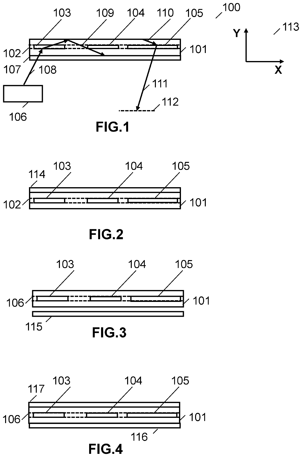
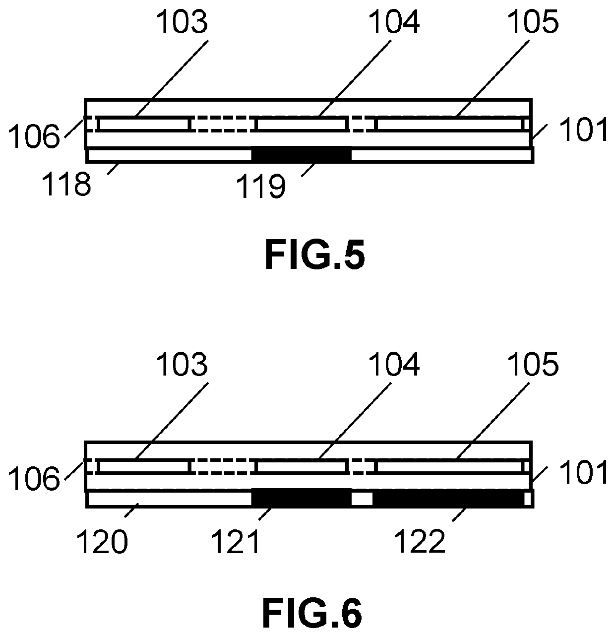
Waveguides and waveguide displays having a layer for blocking non-image light (i.e. haze) that could otherwise reduce contrast and degrade color gamut and uniformity, while providing high transmission to external light are provided. Many waveguides and displays incorporate at least one light control layer applied to at least one external surface of said waveguide and overlapping at least a portion of said at least one grating, to divert or block scattered light from said set of gratings that might otherwise enter said eyebox.

Description

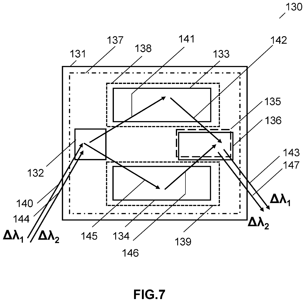
CROSS-REFERENCE TO RELATED APPLICATIONS[0001]The present application claims priority to U.S. Provisional Application No. 62 / 792,309, filed Jan. 14, 2019, the disclosure of which is incorporated herein by reference.FIELD OF THE INVENTION[0002]The present disclosure generally relates to waveguide devices and, more specifically, to a holographic waveguide display using a light control layer to limit haze.BACKGROUND OF THE INVENTION[0003]Scatter from particulates suspended in holographic gratings, and HPDLC gratings in particular, can result in haze, which reduces image contrast, color fidelity, and brightness uniformity. The main contributor to haze can stem from the fold grating where the large number of beam grating interactions for beam folding and expansion can lead to millions of scattering events. Much of this scatter can find its way into the eye box of the display. In contrast, input and output gratings typically have a very small number of beam grating interactions.[0004]The u...

Claims


Application Information

Patent Timeline
IPC IPC(8): G02B27/01G02B5/32
CPCG02B5/32G02B2027/0118G02B27/0103G02B2027/0112G02B2027/0174G02B27/4272
Inventor WALDERN, JONATHAN DAVIDGRANT, ALASTAIR JOHNPOPOVICH, MILAN MOMCILO
Owner DIGILENS
Learn More