

Imaging apparatus, and control method and control program therefor
a technology of imaging apparatus and control method, which is applied in the direction of viewfinders, television systems, instruments, etc., can solve the problem that imaging cannot be performed to provide a sense of presen
- Summary
- Abstract
- Description
- Claims
- Application Information
AI Technical Summary
Benefits of technology
Problems solved by technology
Method used
Image

Examples
first embodiment
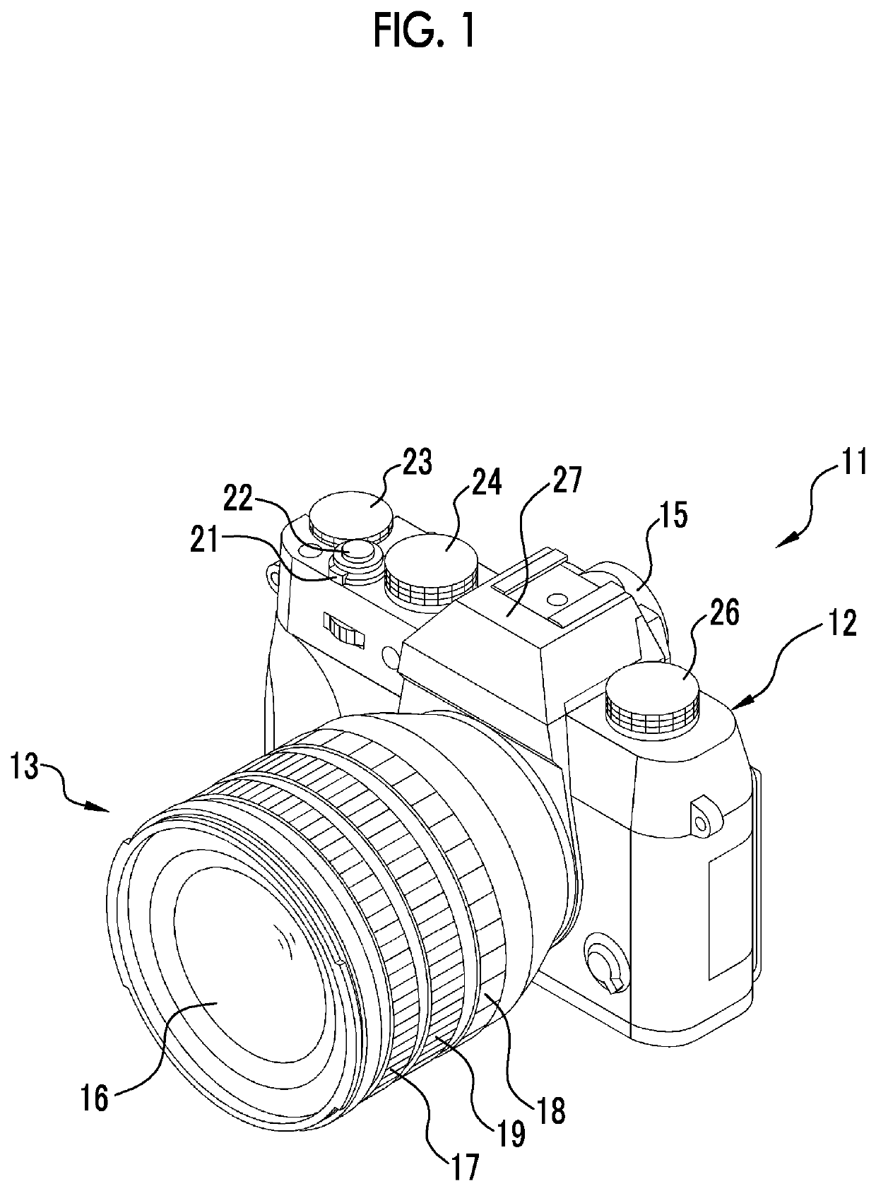
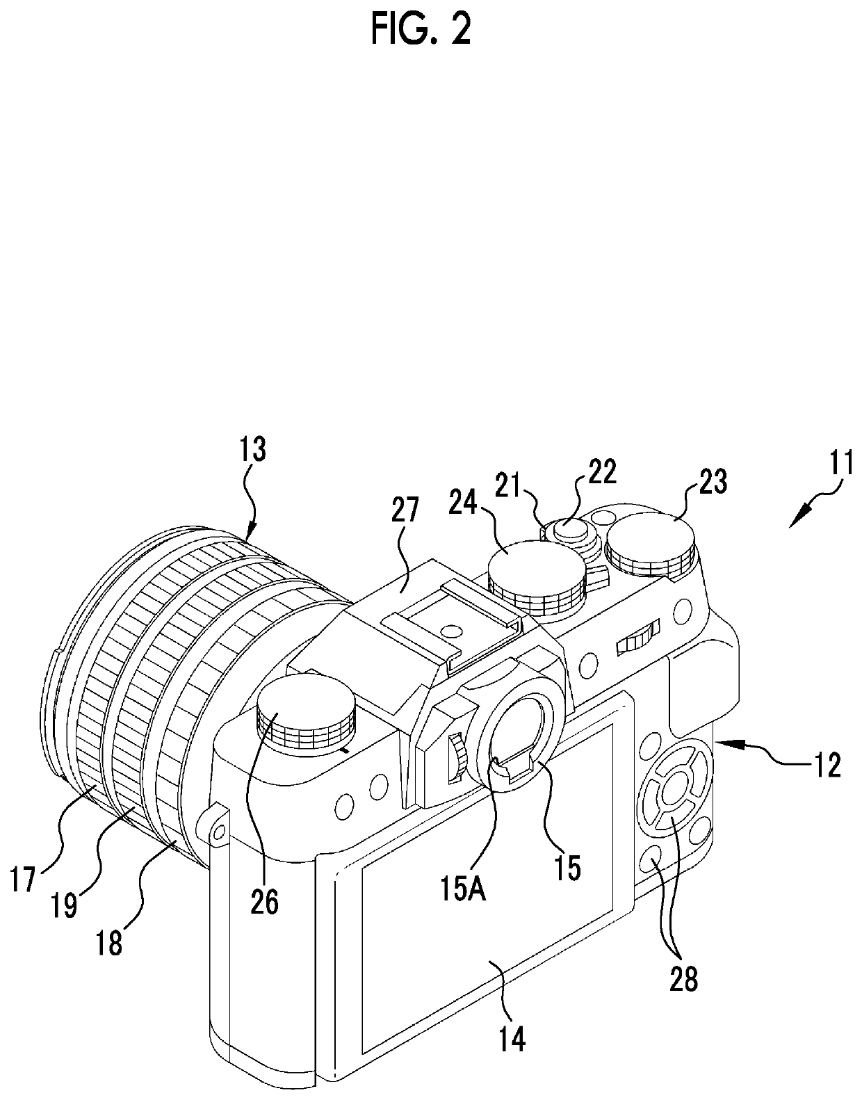
[0041]In FIGS. 1 and 2, a digital camera 11 comprises a camera body 12 (apparatus body), a lens barrel 13, a rear display unit 14, and a finder unit 15.
[0042]The lens barrel 13 is provided on a front surface of the camera body 12, and holds an imaging optical system 16. A focus ring 17, a stop ring 18, and a zoom ring 19 are provided on an outer periphery of the lens barrel 13.
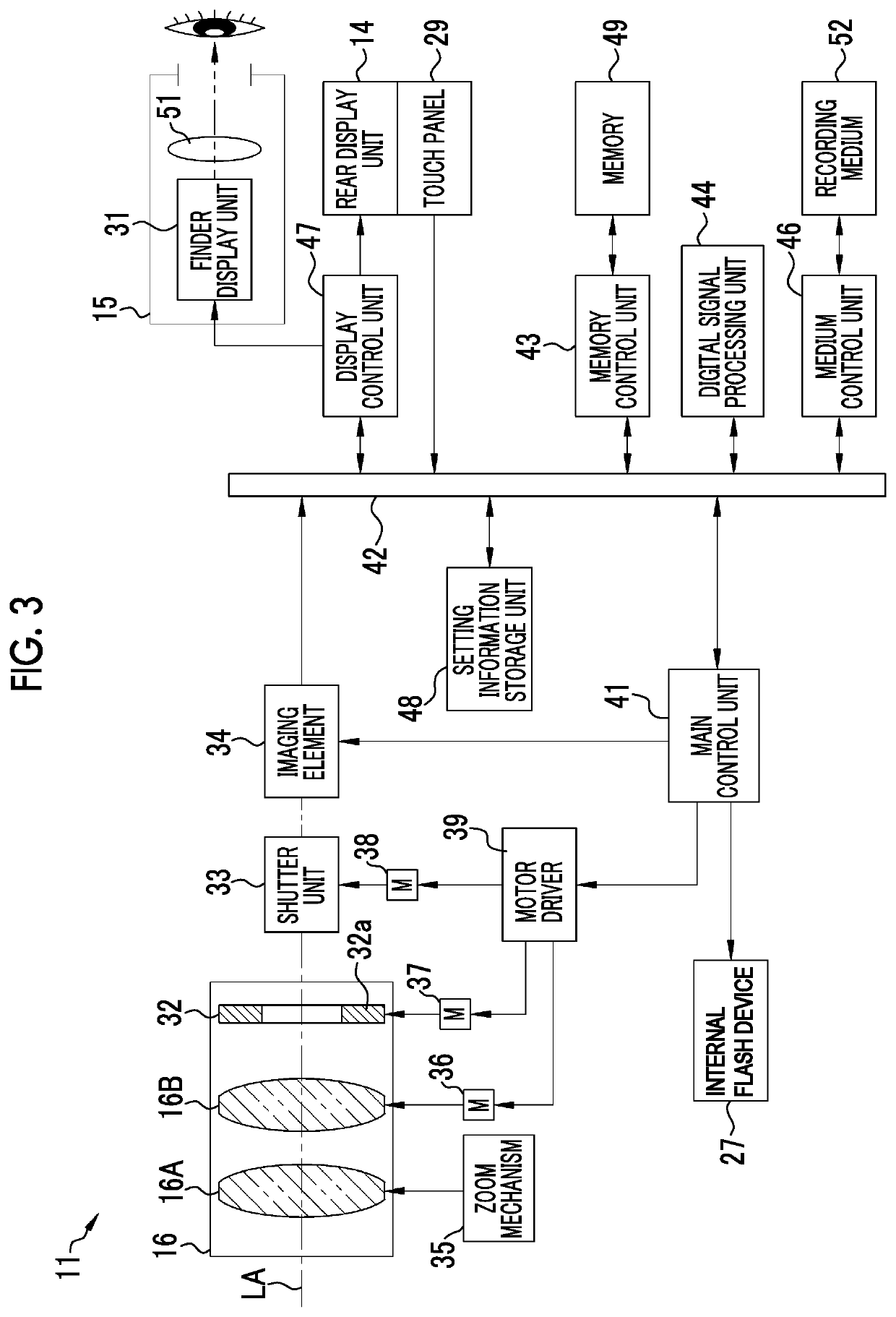
[0043]The rear display unit 14 is provided on a rear surface of the camera body 12 and is used for playback of a captured image, display of a live view image, display of a setting menu, and the like. The rear display unit 14 is constituted of, for example, an LCD panel. A touch panel 29 (see FIG. 3) is attached to a surface of the rear display unit 14, and an input instruction from the touch panel 29 is transmitted to a main control unit 41.
[0044]A power lever 21, a release switch 22, an exposure correction dial 23, a shutter speed dial 24, an ISO sensitivity dial 26, an internal flash device 27, and the like ...
second embodiment
[0086]In a second embodiment described below, in a case where the amount of movement based on the movement vector of the peripheral portion in the captured image is greater than the amount of movement based on the movement vector of the principal subject image, the display range of the live view image on the finder display unit is reduced, and the imaging information is displayed on the finder display unit on a magnified scale.
[0087]As shown in FIG. 8, in the state of the initial setting, the display control unit 47 makes the imaging information D relating to the imaging conditions of the imaging unit be displayed around the maximum display range E0 on the finder display unit 31. In this case, as in the above-described first embodiment, since the live view image is displayed over the entire width of the finder display unit 31, the imaging information D is displayed in an empty space on the upper side or the lower side of the finder display unit 31 so as not to interfere with the liv...
third embodiment
[0090]In the respective embodiments described above, although an example where, in a case where the amount of movement based on the movement vector of the peripheral portion in the captured image is greater than the amount of movement based on the movement vector of the principal subject image, the display range of the live view image on the finder display unit is reduced at a given reduction rate has been described, the invention is not limited thereto. In a third embodiment described below, a speed of a pan operation or a tilt operation is detected, and the reduction rate of the display range is changed according to the detected speed of the pan operation or the tilt operation. In this case, as shown in FIG. 9, a digital camera 55 comprises a speed detection unit 56. The configurations other than the speed detection unit 56 are the same as those in the respective embodiments described above.
[0091]The speed detection unit 56 is constituted of a general acceleration sensor, an angul...
PUM
 Abstract
Description
Claims
Application Information