Inert gas-assisted laser machining of ceramic-containing articles

a technology of laser machining and ceramics, which is applied in the direction of laser beam welding apparatus, manufacturing tools, welding/soldering/cutting articles, etc., can solve the problems of edm struggling to meet ever-tightening requirements, allowing unwanted surface modification, and cold ablation laser machining not solving the problem of surface modification completely, etc., to reduce friction, reduce the area of contact, and reduce the tendency to “optical sticking”

Active Publication Date: 2020-07-23
II VI DELAWARE INC
View PDF0 Cites 2 Cited by
  • Summary
  • Abstract
  • Description
  • Claims
  • Application Information

AI Technical Summary

Benefits of technology

[0024]In another aspect of the invention, and per the embodiments of the instant invention, in a device for handling semiconductor wafers, a portion of the highly flat surface that supports the wafer (“the wafer support surface”), is removed by machining, thereby reducing the area of contact between the support surface and the wafer. This action reduces the friction between these two, and thus the propensity for “optical sticking”. The machining may take the form of a groove or channel, or a plurality of such grooves or channels, or a plurality of holes such as “blind” holes. In this way, a “texture” or controlled roughness is imparted to the support surface. Embodiments of the present invention may use a laser for this texturing, which laser may be a thermal laser, a cold ablation laser, or a laser (thermal or cold ablation) modified with an inert “cover” gas to reduce oxidation of non-oxide materials.

Problems solved by technology

EDM struggles to meet ever-tightening requirements, as described above.
Conventional laser machining meets dimensional requirements but allows for undesirable surface modification.
Cold ablation laser machining does not completely solve the surface modification problem.

Method used


Image

  • Inert gas-assisted laser machining of ceramic-containing articles
  • Inert gas-assisted laser machining of ceramic-containing articles
  • Inert gas-assisted laser machining of ceramic-containing articles

Examples


example 1

Laser Machining Pins in a Si / SiC Wafer Chuck

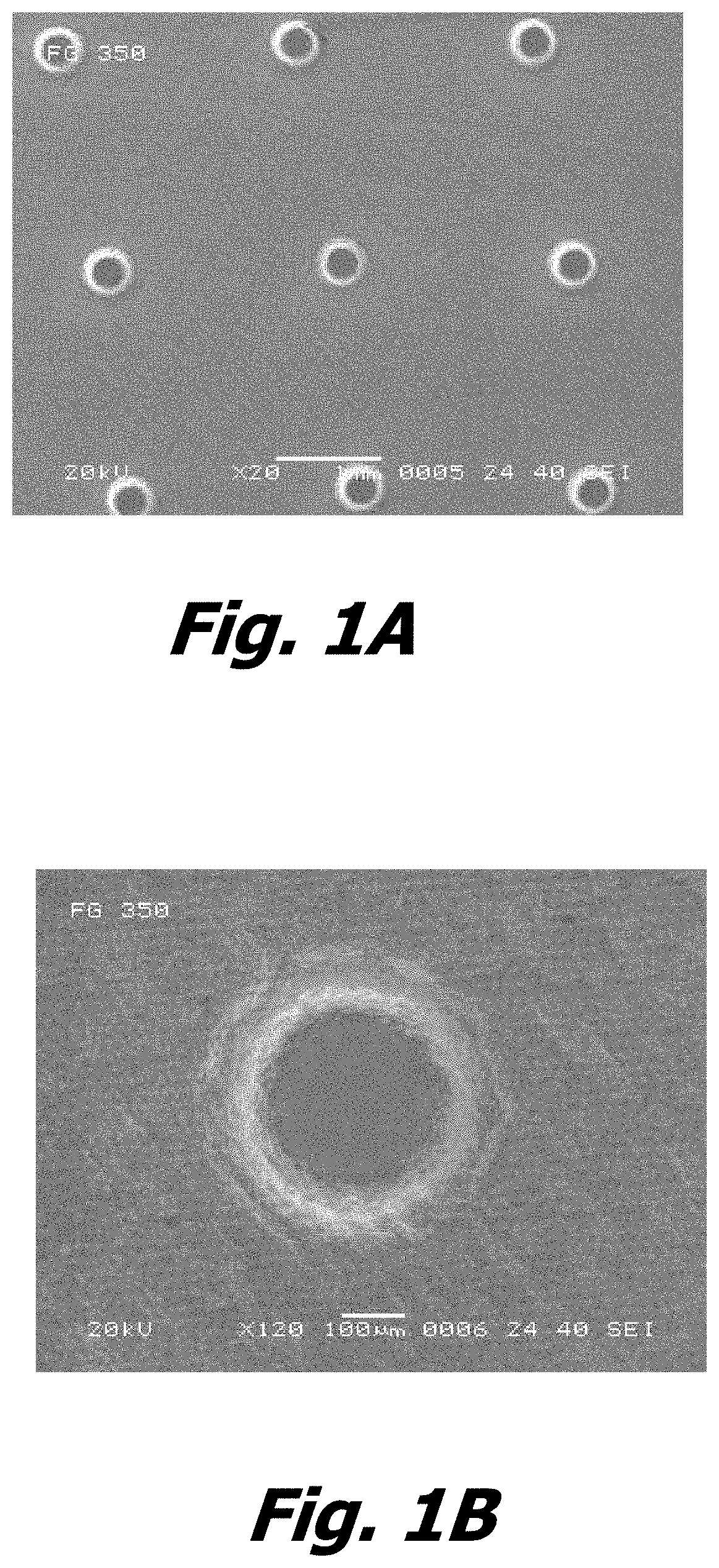
[0086]Refer now to FIGS. 1A and 1B, which are SEM photographs at different magnifications of pins in a Si / SiC wafer chuck that were laser machined according to the instant invention. The laser machining was performed by means of a cold ablation laser apparatus modified or supplemented with a means (e.g., a nozzle) to direct an inert gas (here, argon gas) onto the surface of the Si / SiC material to be machined in the vicinity, zone or region of the laser beam.

[0087]In addition to little-to-no surface modification of the machined surface of the Si / SiC material, the Ar-assisted cold-ablation laser machining provides:[0088]For more precise control of machined features[0089]Much less sub-surface damage[0090]Smoother surface finishes[0091]Much less roughness on feature edges[0092]No evidence of crack or void formation[0093]Avoidance of oxidation and reduced propensity for particle formation.

[0094]By “avoidance of oxidation”, the Applicant means t...

example 2

Comparison of Laser Drilled Holes in Si / SiC

[0095]This example shows the effect of adding an inert gas “assist” to a cold ablation laser machining process.

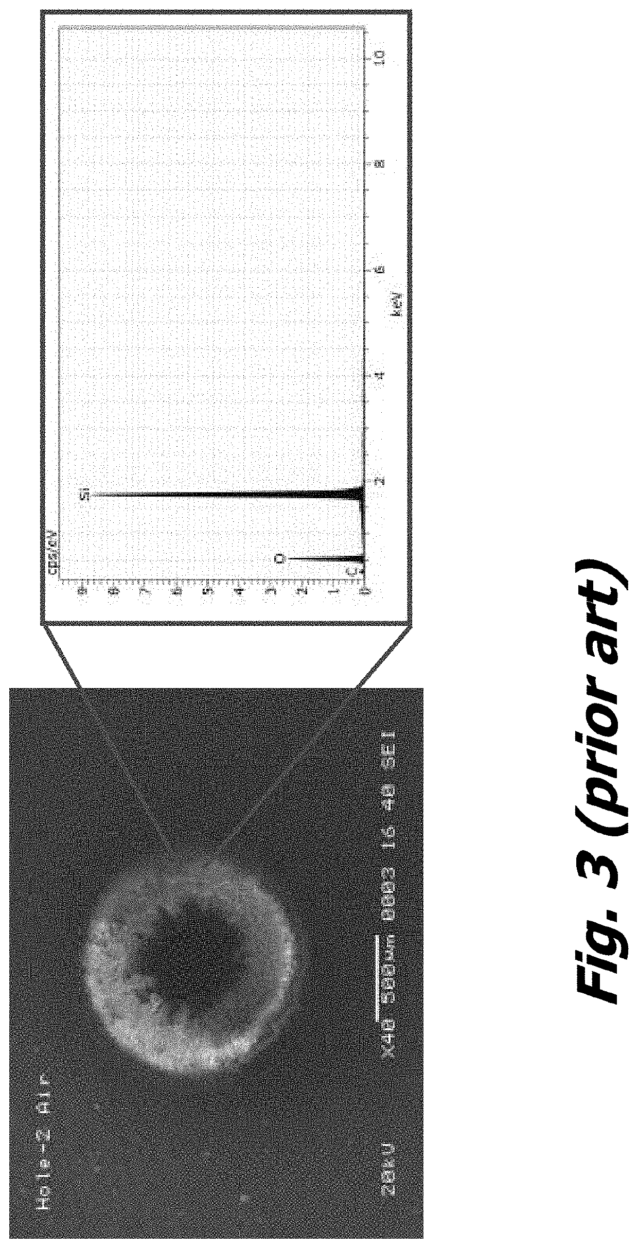
[0096]Here, the process is in drilling a hole in a Si / SiC composite material formed by a reaction-forming process. FIG. 3 shows the process being conducted in air. The left side of the figure is a SEM photo of the hole. The right side of the figure shows the elemental analysis of the edge of the hole according to energy dispersive analysis by x-ray (EDAX).

[0097]Similarly, FIG. 4 shows the process being conducted in flowing argon cover gas. The left side of the figure is a SEM photo of the hole. The right side of the figure shows the elemental analysis of the edge of the hole according to energy dispersive analysis by x-ray (EDAX). Comparing the ratio or relative sizes of the oxygen peak to the silicon peak in FIG. 3 versus FIG. 4, one can see that the oxygen peak is greatly reduced where the argon cover gas was used, indicating muc...

example 3

Comparison of Pocket Cuts in Si / SiC

[0099]This example compares the quality of a “pocket cut” among the modified cold ablation laser machining technique of the instant invention, a prior art cold ablation laser machining process, and a prior art electrical discharge machining process. In each instance, the pocket cut was prepared on a sample of Si / SiC composite material produced by reaction bonding. A pocket cut may be prepared by providing an orthogonal prism of material such as a cube, and proceeding to shave off material on one side to a desired depth but leaving a region near the top surface intact, and then doing the same on an adjacent side surface, again leaving a region near the top surface undisturbed.

[0100]FIGS. 5A, 5B and 5C are SEM photographs at the same magnification of pocket cuts made into the Si / SiC samples by EDM, the prior art cold ablation laser in air, and the instant cold ablation laser machining under protective argon gas flow. The samples are oriented each the...


PUM

PropertyMeasurementUnit
poweraaaaaaaaaa
wavelengthaaaaaaaaaa

Abstract

An article including a ceramic material and featuring a machined surface that is characteristic of cold ablation laser machining, wherein the machined surface exhibits no visible oxidation.A laser machining apparatus and technique based on cold-ablation, but modified or augmented with an inert assist gas, which minimizes the deleterious surface modifications and mitigates the oxide formation associated with laser machining.

Description

CROSS-REFERENCE TO RELATED APPLICATION(S)[0001]This patent document claims the benefit of U.S. Provisional Application Ser. Nos. 62 / 500,482 and 62 / 500,491, each filed on May 2, 2017. Where permitted by law, the entire contents of each of these commonly owned patent applications are expressly incorporated by reference herein..STATEMENT REGARDING FEDERALLY SPONSORED RESEARCH[0002]None.TECHNICAL FIELD[0003]In one aspect, the present invention relates to machining techniques for use on ceramic-containing materials, including composites and glasses. The present invention particularly relates to laser machining techniques.[0004]In another aspect, the present invention relates to machining methods for imparting a controlled roughness to an otherwise flat, smooth surface, particularly in articles or components for handling semiconductor wafers (e.g., silicon) wafers for processing, which could be, but is not limited to, lithography.BACKGROUND ART[0005]As Moore's Law pushes semiconductor fea...

Claims


Application Information

Patent Timeline
Patent Type & Authority Applications(United States)
IPC IPC(8): B23K26/402B23K26/08B23K26/12B23K26/14B23K26/0622B23K26/10B23K26/362C04B41/00C04B41/53C04B41/91H01L21/687
CPCC04B41/0036C04B41/5346B23K26/402B23K26/362B23K26/0876B23K26/0624H01L21/68735B23K26/123B23K26/10C04B41/91B23K26/1464B23K26/14B23K26/36B23K26/40B23K2103/02B23K2103/08B23K2103/50B23K26/364B23K2103/52B23K26/355B23K26/032H01L21/687
Inventor MCDANNALD, AUSTIN SCOTTMASTROBATTISTO, DANIELAGHAJANIAN, MICHAEL K.GRATRIX, EDWARD J.
Owner II VI DELAWARE INC
Why Eureka
Try Eureka