

Display device and television device
a technology for a display device and a television device, which is applied in the direction of transducer diaphragms, identification means, instruments, etc., can solve the problems of difficult to output the desired sound pressure, easy to split vibration, and less likely to follow the acoustic wave frequency of material vibration, etc., to achieve thin devices, improve acoustic characteristics, and easy control of vibration modes
- Summary
- Abstract
- Description
- Claims
- Application Information
AI Technical Summary
Benefits of technology
Problems solved by technology
Method used
Image

Examples
examples
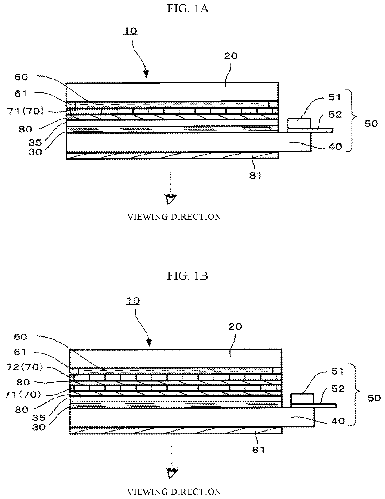
[0166]Each of the display devices 10 of the present invention had a structure including a display module 50 and a first plate-shaped object 20 laminated thereto. The effect of the thicknesses of the two members on acoustic control was examined. The table of FIG. 7 shows the results thereof. The display module 50 and the first plate-shaped object 20 each had sheet thicknesses of 0.2 mm, 0.5 mm, 0.7 mm, 2 mm, and 3 mm.
[0167]FIG. 7 is a table showing the results of the acoustic measurement of glass diaphragms having different thicknesses of the first plate-shaped object and flat-panel display module. As the sheet thickness ratio deviates from the range of 1:10 to 10:1, the results became poorer. The glass diaphragms made with sheet thicknesses of 3 mm and 0.2 mm were poor in reproduction. Meanwhile, when the sheet thickness ratio was closer to 1:1, good results were obtained (see the symbol ◯ in the table).
[0168]The present invention is not limited to the embodiments described above, a...
PUM
 Abstract
Description
Claims
Application Information