Cleaning system for optical surface

a cleaning system and optical surface technology, applied in the field of cleaning systems, can solve the problems of affecting the operation and affecting the quality of the information provided by the sensor or camera, so as to improve the power efficiency and improve the efficiency of the optical surface. , the effect of improving the power efficiency

Inactive Publication Date: 2020-07-30
JETWIPE 2017 IVS
View PDF0 Cites 5 Cited by
  • Summary
  • Abstract
  • Description
  • Claims
  • Application Information

AI Technical Summary

Benefits of technology

[0014]In one embodiment the air flow generator is a low-pressure, high-flow air flow generator. A low-pressure, high-flow air pump makes the system more power efficient than the existing high-pressure solutions. If the pressure is a static pressure when the cleaning system operates, the power efficiency may be further improved.
[0015]The optical surface may be a substantially circular lens, such as a slightly convex camera lens. For such optical surfaces, the present disclosure presents a number of particularly useful embodiments. The cleaning system may comprise an arm for holding the at least one nozzle, wherein the nozzle is mounted at one end of the arm. The arm may be adjustable and / or controllable to elect the jet of air from various angles and / or distances with respect to the optical surface with respect to the optical surface. By adjusting distances and angles the air jet can be adjusted to operate efficiently on the optical surface. For example, the point from which the air jet is generated may rotate in a circular movement around the surface or clean surfaces which have more dirt than others more thoroughly based on information from the sensor. The arm may also be a robotic arm and may for example be programmed to move in a predefined pattern or in response to input from sensors providing information about e.g. the level of degradation of the surface due to dirt etc.

Problems solved by technology

The optical surfaces are typically placed on a vehicle exterior surface and are often exposed to dirt, mud, ice, dust etc. which may accumulate on the optical surface and deprive the quality of the information provided by the sensor or camera.
There are various types of devices for washing a glass or lens of vehicle-mounted camera,. by applying water or air, However, the known cleaning devices are associated with a number of issues and disadvantages.
For example, the air flow, the power efficiency and, the cleaning capabilities are not optimal.

Method used


Image

  • Cleaning system for optical surface
  • Cleaning system for optical surface
  • Cleaning system for optical surface

Examples


Embodiment Construction

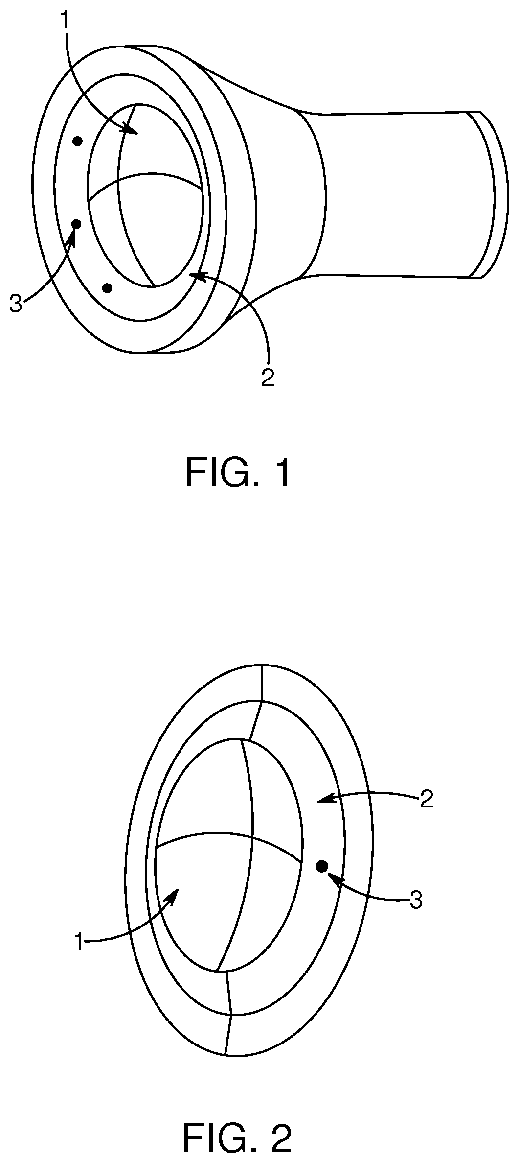
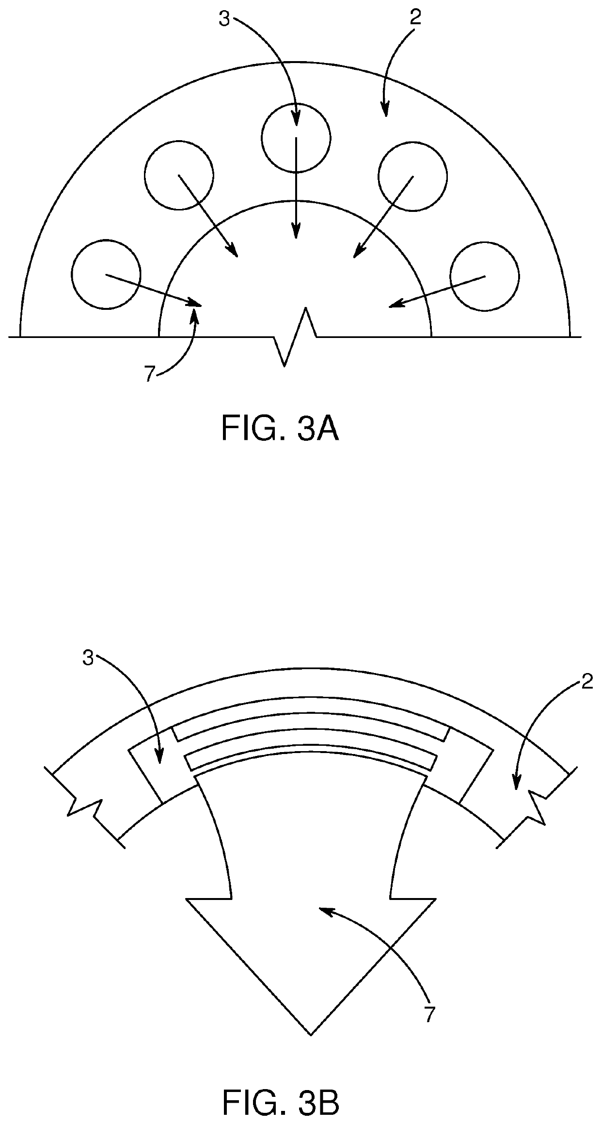
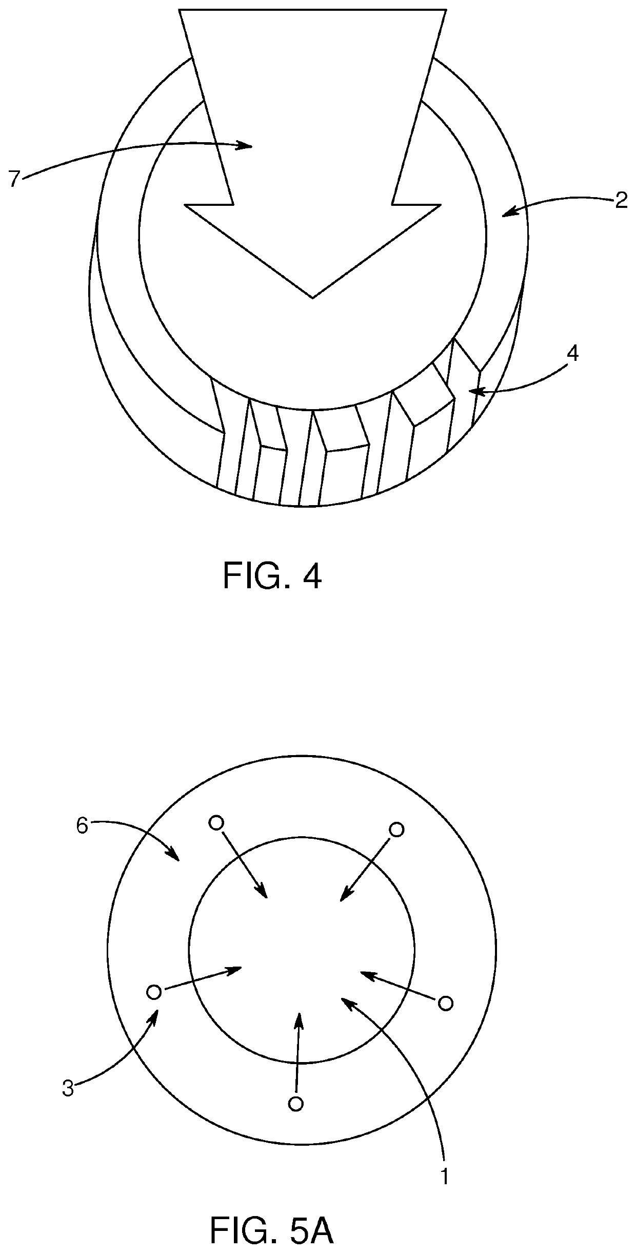
[0032]The present disclosure relates to a cleaning system for cleaning an optical surface, such as an optical lens of a vehicle camera or sensor, comprising:[0033]at least one nozzle arranged to eject a jet of air towards the surface; and[0034]at least one air flow generator connected to the at least one nozzle trough at least one duct and arranged to generate an air flow to the at least one nozzle.

[0035]In particular the system may be applied to a car. Sensors and cameras are often placed on or integrated in autonomous cars. These sensors and cameras would benefit from the presently disclosed cleaning system and cover assembly,

[0036]Preferably, the system has the capability of ejecting a cleaning fluid in the jet of air, either in the duct, nozzle or outside the nozzle. The cleaning fluid may comprise hydrophobic liquid, which can be applied to the surface to be cleaned and makes it easier to remove water from the surface. The nozzles and the at least one duct may be used to distri...


PUM

PropertyMeasurementUnit
pressureaaaaaaaaaa
pressureaaaaaaaaaa
angle of incidenceaaaaaaaaaa

Abstract

A cleaning system for cleaning an optical surface, such as an optical lens of a vehicle camera or sensor, includes at least one nozzle arranged to eject a jet of air towards and/or parallel to the surface; and an outer protective cover layer. The cover layer is mountable on the optical surface and configurable in: a closed configuration, wherein the cover layer and optical surface form a cleaning space between the cover layer and optical surface and the optical surface is protected by the protective cover layer; and an open configuration wherein the optical layer is exposed. A cover assembly is also provided for a vehicle sensor(s) or an image sensitivity part of a camera(s).

Description

REFERENCE TO RELATED APPLICATIONS[0001]This application is a U.S. national stage application of PCT / EP2018 / 064461, tiled Jun. 1, 2018, which claims priority to European application No. EP17174249.7, filed Jun. 2, 2017, the entire content of both of which is incorporated herein by reference.FIELD OF THE INVENTION[0002]The present disclosure relates to a cleaning system, in particular an air jet-based cleaning system, for cleaning an optical surface, such as an optical lens of a vehicle camera or sensor. The disclosure further relates to a cover assembly for a vehicle sensor or image sensitivity part of a camera.BACKGROUND OF THE INVENTION[0003]Vehicles are increasingly in need of sensing its environment for example in order to enhance the driver's vision through cameras, or for autonomous cars capable of navigating partly or completely without human input Autonomous cars use a variety of techniques to detect their surroundings, such as radar, laser light, GPS, odometry, and computer ...

Claims


Application Information

Patent Timeline
Patent Type & Authority Applications(United States)
IPC IPC(8): B60S1/56B60S1/54G02B27/00
CPCB60S1/56G02B27/0006B60S1/54
Inventor WALSØE, JANFOGED, MORTEN VENDELBONIELSEN, DAN MØNSTER
Owner JETWIPE 2017 IVS
Why Eureka
Try Eureka