Fluid flow control valve equipped with a conical flap and system comprising such valve

a technology of fluid flow control and conical flap, which is applied in the direction of mechanical equipment, pressure relieving devices on sealing faces, transportation and packaging, etc., can solve the problems of complex deployment methods, inability to quickly move the butterfly, and disruption of the flow of fluid

Active Publication Date: 2020-08-13
LIEBHERR AEROSPACE TOULOUSE
View PDF0 Cites 7 Cited by
  • Summary
  • Abstract
  • Description
  • Claims
  • Application Information

AI Technical Summary

Benefits of technology

[0082]According to this variant, the symmetrical configuration of the magnetic drive also makes it possible to act on the flap as a magnetic bearing, thus making it possible to attenuate the vibrations of said flap when the valve is subjected to vibrational excitation, which is the case, for example, for aeronautical applications.
[0083]Advantageously and according to the invention, said valve further comprises at least one contactless Hall effect sensor making it possible to measure a variation in magnetic field in order to obtain a change in state of the limit switch signal.
[0084]Such a Hall effect sensor arranged in the valve body advantageously makes it possible to provide the valve with a limit switch detection functionality.

Problems solved by technology

Since the butterfly axis crosses the valve body, this implies deploying complex means to manage any leaks at the bearing of this axis.
However, this type of valve comprises, on the one hand, a butterfly making it possible to obtain a half-moon opening section, the circulation of the fluid is therefore disrupted by the presence of the butterfly.
On the other hand, the movement of the butterfly cannot be achieved quickly and therefore the variation of the fluid passage section is slowed down.
However, in view of the difficulty in actuating such an axial flap, this type of valve is not widespread.

Method used


Image

  • Fluid flow control valve equipped with a conical flap and system comprising such valve
  • Fluid flow control valve equipped with a conical flap and system comprising such valve
  • Fluid flow control valve equipped with a conical flap and system comprising such valve

Examples


Embodiment Construction

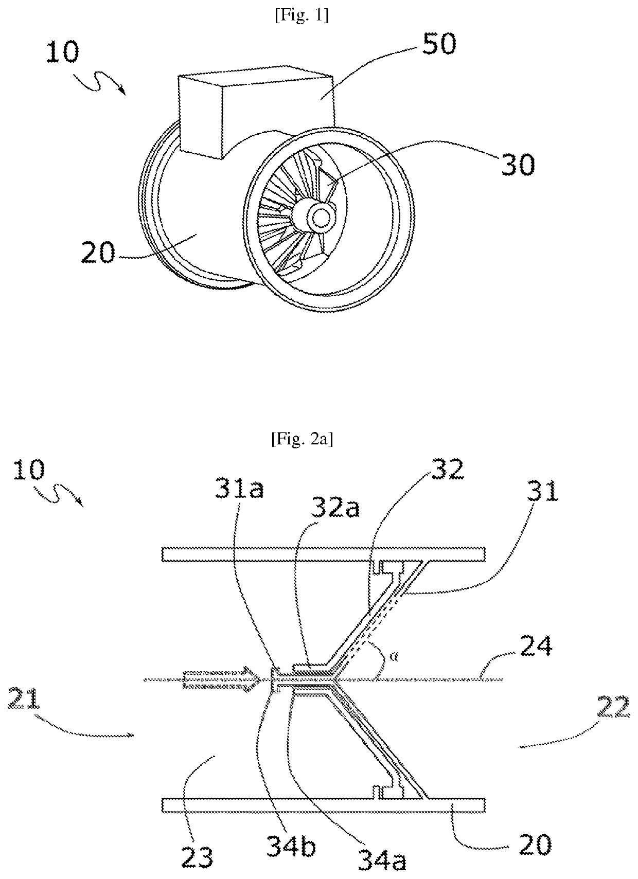
[0101]For the sake of illustration and clarity, the scales and proportions are not strictly adhered to in the figures. Throughout the following detailed description, with reference to the figures, unless otherwise indicated, each element of the valve is described as it is arranged when said conical flap is rotationally movable on a fixed support in the valve body and is controlled by an actuator arranged outside the valve body.

[0102]The terms “axial” and “radial” are used with reference to the axial direction, which is defined by the direction of the fluid circulation channel extending between the fluid inlet and the fluid outlet of the valve body.

[0103]In addition, identical, similar or analogous elements are denoted using the same reference signs throughout the figures.

[0104]Throughout the following description, the control valve described is a valve of an air-conditioning system of an aircraft. However, in other embodiments, the valve can be a control valve for a fluid other than...


PUM


Abstract

A valve for controlling a fluid flow includes a valve body, a shutter component configured to be able to transition from an open position allowing the circulation of fluid, to a closed position preventing the circulation of fluid. The component is characterized in that it includes a fixed conical support integral with the valve body, a conjugate conical flap rotationally movable relative to the fixed support, and fluid passage apertures respectively arranged in the conical flap and in the fixed support, and an actuator of the shutter component adapted to be able to control the position of the shutter component.

Description

CROSS REFERENCE TO RELATED APPLICATIONS[0001]This application claims priority under 35 U.S.C. § 119(a) to French patent application number 1901253, filed on Feb. 8, 2019, the entire teachings of which are incorporated herein by reference.BACKGROUND OF THE INVENTIONTechnical Field of the Invention[0002]The invention relates to a valve for controlling a fluid flow, in particular an air flow. The invention relates in particular to a conical-shaped valve for controlling a fluid flow. The invention also relates to an air conditioning system for an aircraft cabin and to a ventilation system comprising such a valve.Description of the Related Art[0003]An air-conditioning system for an aircraft cabin generally comprises a device for collecting compressed air on at least one compressor of an aircraft propulsion engine (or an air collection device connected to a scoop of the aircraft) and an air-cycle turbine engine comprising at least one compressor and one turbine, the compressor being suppl...

Claims


Application Information

Patent Timeline
Patent Type & Authority Applications(United States)
IPC IPC(8): F16K3/34F16K3/22B64D13/06B61D27/00
CPCF16K3/22F16K3/34B61D27/0018B64D13/06F16K3/188F16K39/045
Inventor LAFOND, ERICARNAUD, ADRIENWOJCIESZONAK, RÉMI
Owner LIEBHERR AEROSPACE TOULOUSE
Why Eureka
Try Eureka