Bullet with improved aerodynamics

a technology of aerodynamics and bullets, applied in the direction of ammunition projectiles, weapons, projectiles, etc., can solve the problems of limiting the diameter of the meplat, speed variability along the flight path, and not being addressed

Active Publication Date: 2020-08-13
HORNADY MFG
View PDF8 Cites 3 Cited by
  • Summary
  • Abstract
  • Description
  • Claims
  • Application Information

AI Technical Summary

Benefits of technology

[0015]It is an objective of the present invention to provide a b...

Problems solved by technology

Current understanding of bullet features has mainly focused on the implications on the average or overall shape drag, but has not addressed the influence these features have on the variability of t...

Method used


Image

  • Bullet with improved aerodynamics
  • Bullet with improved aerodynamics
  • Bullet with improved aerodynamics

Examples


Embodiment Construction

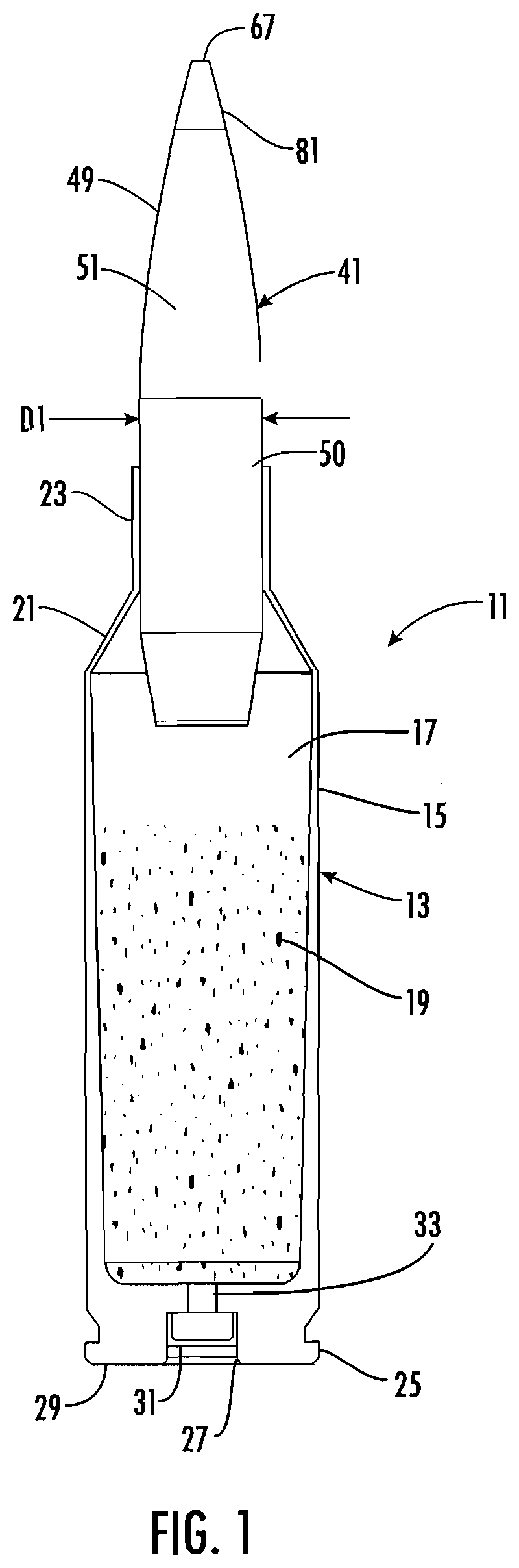
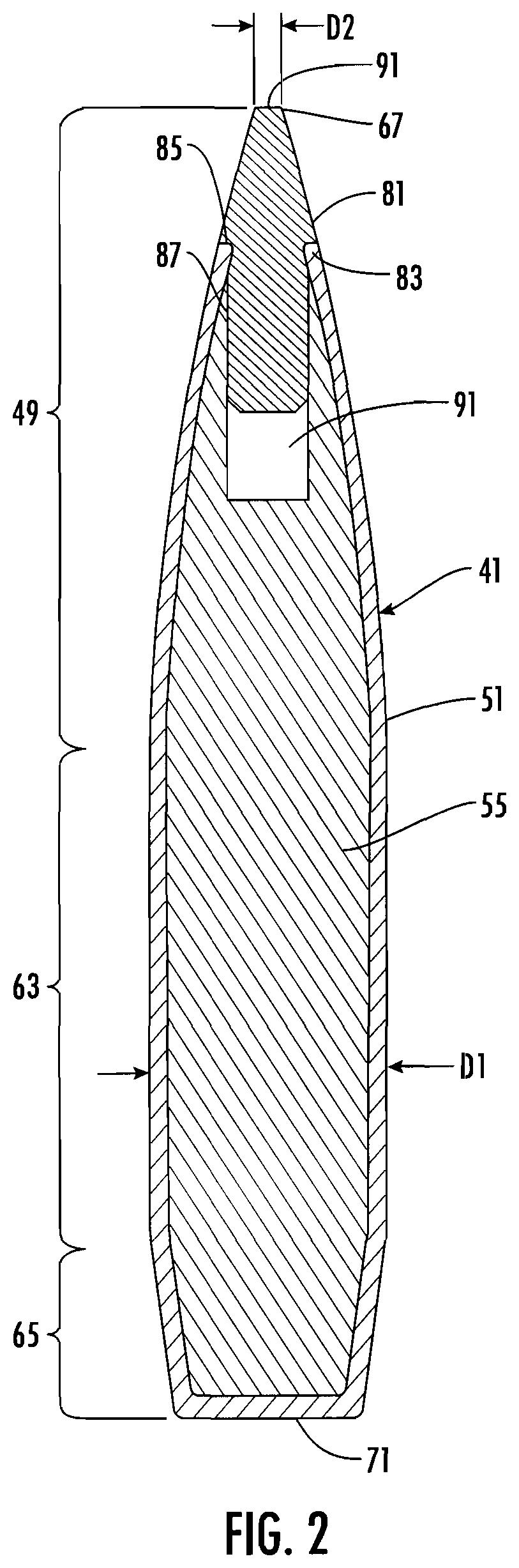
[0031]FIG. 1 illustrates a centerfire rifle cartridge, designated generally 11, having a case (often also called a casing) 13 with a sidewall 15 partially defining an interior chamber 17 for holding propellant 19. While a necked down case 13 is illustrated, any suitable case can be used. The illustrated case 13 includes a shoulder 21 and a neck 23. The case 13 includes a base 25 having a primer pocket 27 opening onto the bottom 29 thereof. A primer 31 is positioned within the primer pocket 27 and has the ignition end thereof exposed to the flash hole 33, which provides a primer flame a path between the primer pocket 27 and the interior 17, whereby the flame from the primer 31, when initiated by the firing pin of a firearm (not shown) striking the primer 31, passes through the flash hole 33 and ignites the propellant 19. While the primer 31 and flash hole 33 are shown as a Boxer style primer, any suitable primer arrangement can be used. A bullet 41 is seated in the neck 23 of the cas...


PUM


Abstract

A bullet with a blunt meplat with reduced drag coefficient relative to a non-blunt meplat with improved speed consistency during flight shot to shot.

Description

PRIORITY CLAIM[0001]In accordance with 37 C.F.R. 1.76, a claim of priority is included in an Application Data Sheet filed concurrently herewith. Accordingly, the present invention claims priority to U.S. Provisional Patent Application No. 62 / 804,257, entitled “BULLET WITH IMPROVED AERODYNAMICS”, filed Feb. 12, 2019. The contents of the above referenced application are incorporated herein by reference in its entirety.FIELD OF THE INVENTION[0002]A bullet with improved consistency of aerodynamics during flight is provided.BACKGROUND OF THE INVENTION[0003]Bullets are well known in the art. A bullet is the projectile that is discharged from the barrel of a firearm such as a rifle. The bullet is driven into the rifled portion of a barrel by high pressure gas generated from the burning of a propellant (gun powder or powder), which is typically ignited by a primer, as is well known in the art. The term “bullet” is often used to incorrectly refer to a complete ammunition cartridge. A cartrid...

Claims


Application Information

Patent Timeline
IPC IPC(8): F42B10/46F42B10/44
CPCF42B10/44F42B10/46F42B12/34
Inventor THIELEN, JOSEPHQUINLAN, JAYDENDAMMAN, RYAN
Owner HORNADY MFG
Why Eureka
Try Eureka