Minigenerator

a technology of electric generator and battery pack, which is applied in the field of powering electrosurgical and electrocautery tools and instruments, can solve the problems of inability to provide the amount of power needed for more intensive surgeries in larger organs, and the bulky instrument is too large,

Inactive Publication Date: 2015-12-01
CHEST INNOVATIONS
View PDF10 Cites 1 Cited by
  • Summary
  • Abstract
  • Description
  • Claims
  • Application Information

AI Technical Summary

Benefits of technology

[0012]The cordless nature of the entirely battery-powered generator provides safety improvements for both the patient and healthcare providers (surgeon and operating room staff). There are no cords for anyone to trip over and there is no risk of frayed wires or leaking voltage from poorly insulated or worn wires. The electric circuitry of the generator of the present invention has also been specially designed to perform at reduced voltage levels. The system can run off of a battery in the range of 6 volts to 24 volts and all voltage levels in the circuitry are low, at battery level, until the very last transformer (see last transformer T2 in FIG. 2 final output diagram). Conventional generators with wires that rely on electrical energy from wall outlets typically work with 100-250 volts (V) alternating current (AC). Thus, the present design reduces widespread higher voltages.
[0013]Other advantages of the cordless battery-powered design of the generator are that it is much more portable. Physicians working out of several hospitals, clinics, and out-patient offices (as many do) can carry the same preferred instrument with them from place to place, thereby building skill and confidence from using the same piece of equipment. Generator portability also reduces the need for a separate instrument and generator at every site or on every floor of a facility, thereby reducing overhead expense which is passed along to maintain lower procedure costs for patients and insurance companies. The generator system is so small compared to conventional plug-in wall units it is even easy to travel with including by plane transportation. Surgeons should prefer this cordless battery-powered generator because it drastically increases their safe range of motion during surgery, giving them greater ability to “dance” about the operating room and flex / bend / turn as necessary to obtain the best treatment angles without worrying about tripping on wires, getting cords tangled, or traversing the patient with electrically charged cords. Greater instrument controllability results in more precise and accurate cutting (more hit, less miss when aiming at a target) which consequently results in less bleeding from hitting unintended vessels and other structures. In addition to less bleeding, there is less structural damage to unintended structures. Better maneuverability also enables improved linear cutting with less deviation from a path along a line.
[0015]The electronic circuitry of the generator is arranged in an interconnected closed loop functional feedback system such that power drained from the battery and converted by the converter can be adjusted as necessary to maintain a desired level of current or power supply to the final output. This internal system can also be connected with another external component that monitors an external variable, in a patient's body, that is impacted by the final output current or power. For example, a thermocouple might be used to monitor the temperature of a site in a patient's body. The temperature of a site in contact with the electrosurgical instrument is influenced by the power provided by the battery and the current provided to the final output. By providing Dynamic Temperature Control (DTC) and Dynamic Power Control (DPC) the present invention stabilizes the temperature at an optimal level (or range) while using the minimum amount of power necessary. Resistance is another variable that can be measured by a sensor to monitor the condition of the tissue to ensure it stays within safe ranges while providing the best therapeutic benefit.
[0016]This feedback system saves energy by providing no more energy than is necessary to maintain a given level of current or power to the final output or to maintain the value of a variable that measures a characteristic of tissue in a patient's body at a desired therapeutic level. The hydrated condition of live tissues in a patient's body allows them to conduct electricity and permits a reduction in power necessary for effective treatment compared to desiccated tissues with little or no conduction. However, the extent of hydration and the resistance of tissues changes over the course of treatment and can change abruptly. These changes impact the power requirements to achieve the same effects. Continual feedback provides for the necessary power adjustments to maintain constant therapeutic benefits and avoid dangerous extremes that could cause unwanted outcomes including charring. A more energy-efficient instrument also provides an economic benefit by reducing power costs.

Problems solved by technology

These attempts have confronted the dilemma in that eliminating the wall outlet electrical power source and relying completely on battery power typically makes the instrument so bulky that it is no less awkward to use than instruments attached to wires.
Alternatively, providing a smaller battery to make the instrument easier to handle may be okay for more refined smaller scale surgical work but current circuitry designs and modes of usage cannot provide the amount of power necessary for more intensive surgeries in larger organs.
The array of surgical procedures compatible with such a design is limited.
Thus, the advances of this system, if any, seem marginal.
Typical voltages coming from a wall electrical outlet are much higher than the maximum voltages of reasonably-sized batteries and passing such a high voltage through a trocar cannula adapter unit in proximity to the patient could be dangerous.
However, the system is not truly wireless in that wires exist, it is just that they are divided into separate discrete segments, hidden, and insulated.
A drawback of this system is that the instrument itself does not contactably couple to the power supply.

Method used


Image

  • Minigenerator
  • Minigenerator
  • Minigenerator

Examples


Embodiment Construction

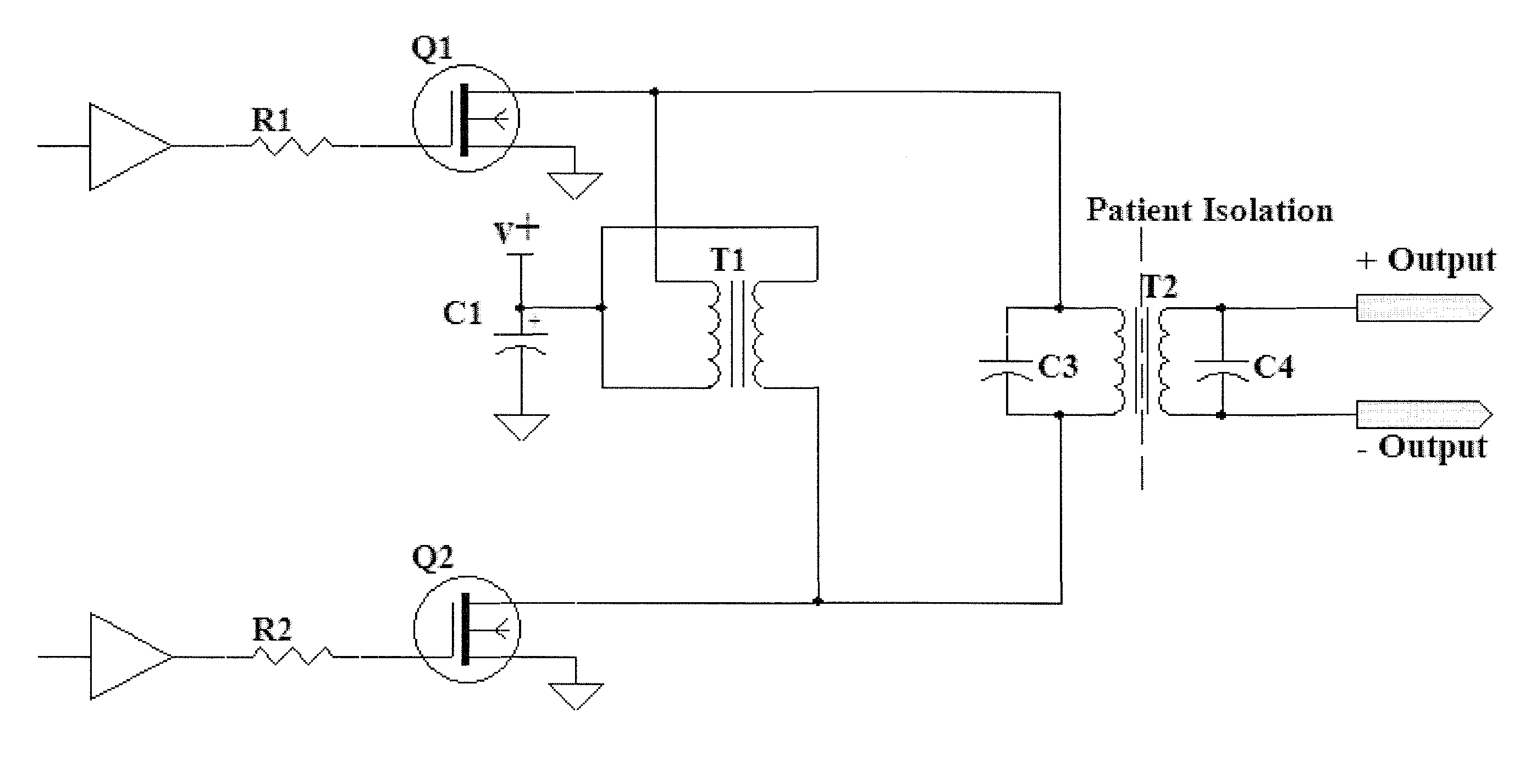
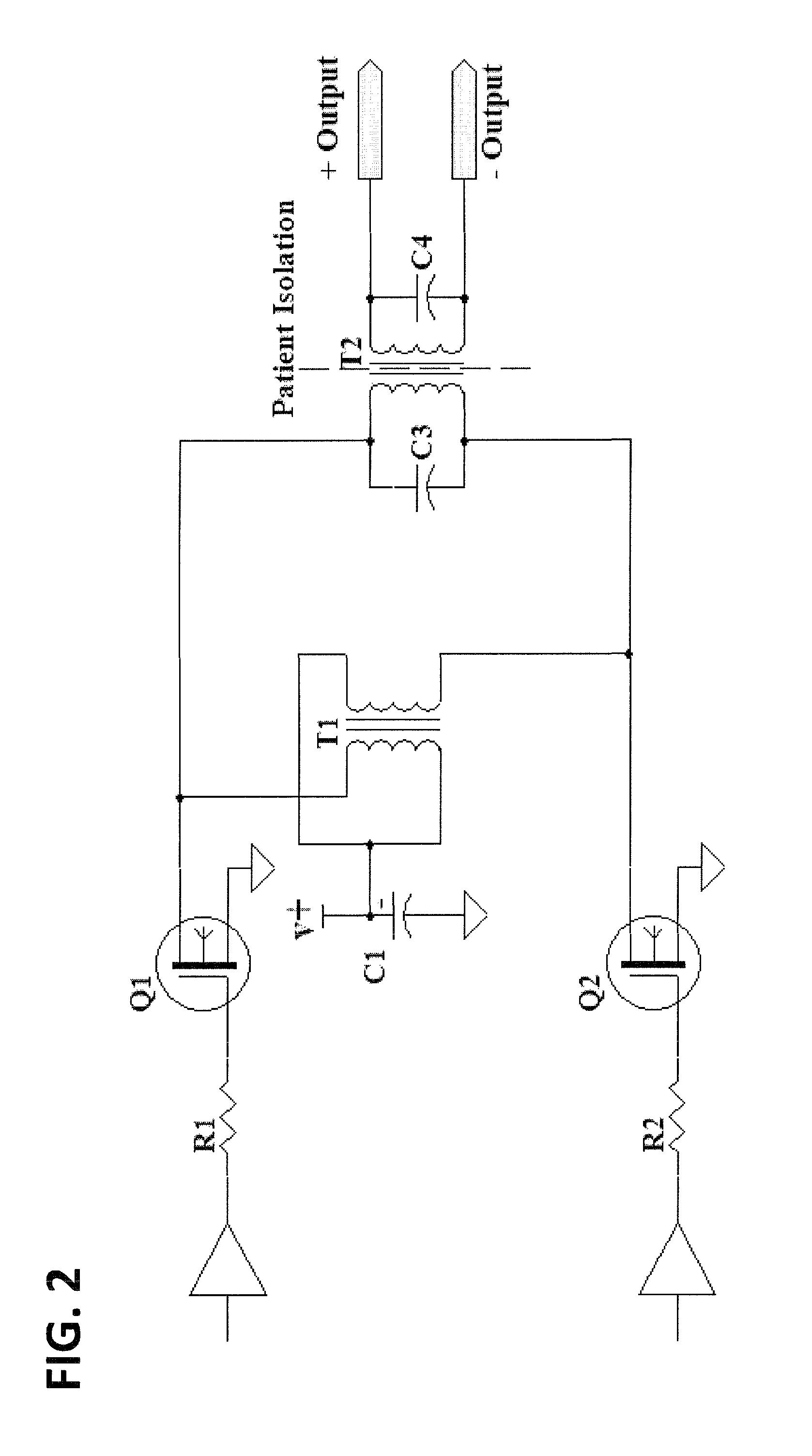
[0025]The design has been optimized for safe, energy-efficient battery operation. All voltage levels in the circuitry are low, at battery level, until the very last transformer T2 (see the final output diagram shown in FIG. 2 illustrating how the last transformer T2 is isolated). The last transformer multiplies the voltage and isolates the patient from the entire circuit. The output stage is simple, but efficient, ideal for battery operation. The use of a “swinging choke” T1 (see FIG. 2) provides the necessary positive and negative outputs by using only two Field Effect Transistors (FETs).

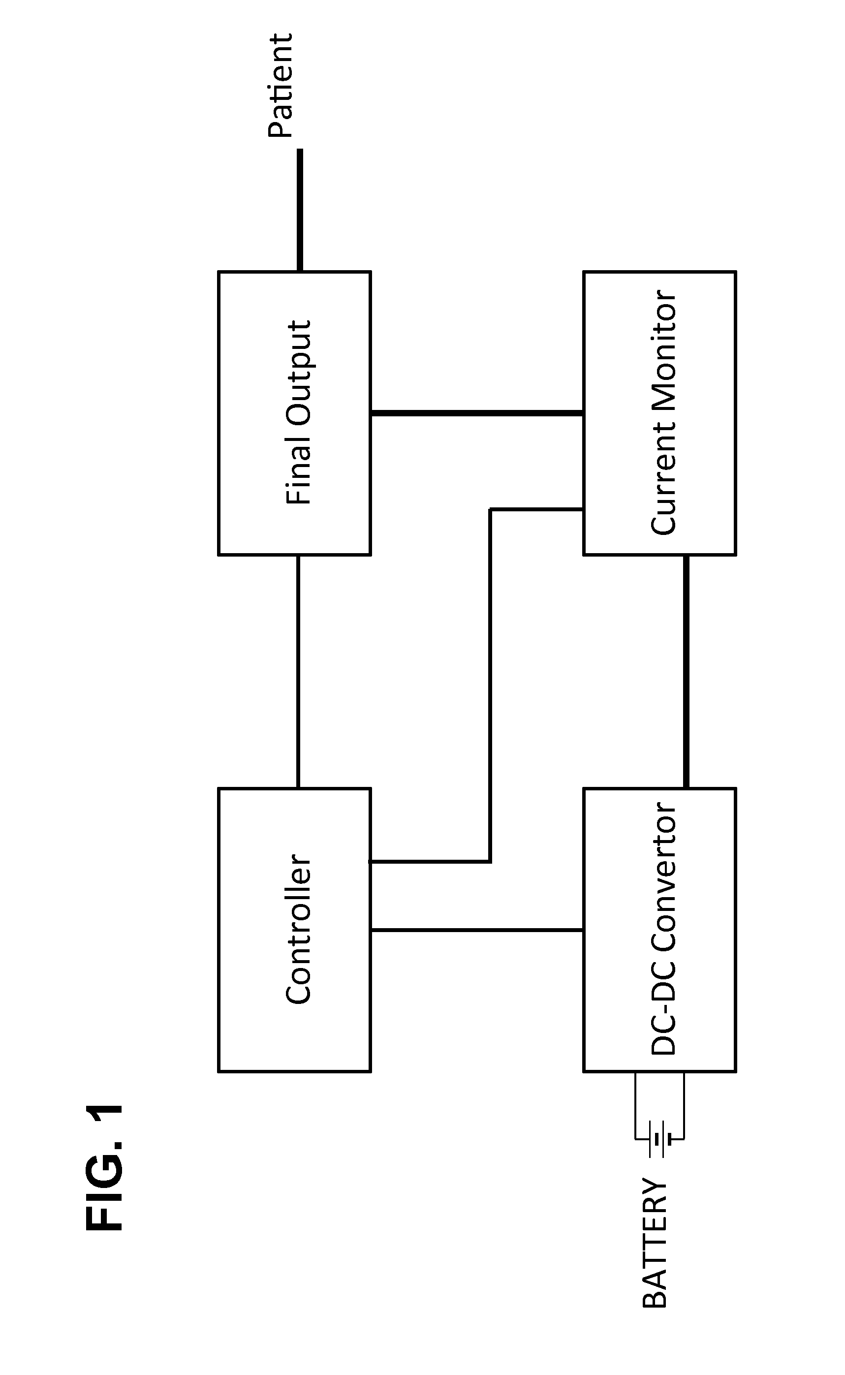
[0026]Using a wide range input DC-to-DC converter design, the latest battery technology can be utilized. Any battery input from about 6 volts up to 24 volts can be accommodated. The output of the DC-to-DC converter does not vary with changes in the input. Therefore the unit can provide an energy output (i.e. radiofrequency or RF output) that is independent of battery voltage. This fixed output feat...


PUM


Abstract

The present invention provides an Electro Surgical Generator (ESG) optimized for lung biopsy. The ESG is exclusively battery operated and fits within the handpiece of modern endoscopic electrosurgical / electrocautery instruments, thereby avoiding wires, adapters, and coupling mechanisms. The ESG is adaptable to generate different waveforms that vary with respect to frequency, pulse width, amplitude, etc. through the use of timing circuits and voltage control (i.e. transformers). The ESG is both energy-efficient and safe. A closed loop feedback system featuring a monitor and controller ensure no more power than necessary is provided to achieve a goal current level. Dynamic Power Control (DPC) and Dynamic Temperature Control (DTC) systems vary power to maintain temperature with the lowest possible power. These features prolong battery life and guard against tissue damage. The generator includes other safety features such as resiliency against and the ability to overcome single fault events such as short circuits.

Description

CROSS-REFERENCE TO RELATED APPLICATIONS[0001]This application is a continuation of Ser. No. 12 / 696,573, filed Jan. 29, 2010, now allowed, the application being incorporated herein in its entirety by reference.BACKGROUND OF THE INVENTION[0002]1. Field of the Invention[0003]The present invention relates to means for powering electrosurgical and electrocautery tools and instruments. More specifically, the present invention relates to cordless battery-powered means for generating power that are compact enough to fit within a handpiece, powerful enough for use in sealing and resecting operations in the lungs, and safe enough to provide risk reduction incentives over conventional generator systems. Most specifically, the present invention focuses on the aspects of the electrical circuitry design for the minigenerator system to provide increased energy efficiency, feedback and alert systems, and adjustable performance parameters to tailor the procedure to the needs of each patient.[0004]2....

Claims


Application Information

Patent Timeline
Patent Type & Authority Patents(United States)
IPC IPC(8): A61B18/12A61B18/00
CPCA61B18/1206A61B2018/00732A61B2018/00642A61B2018/00702A61B2018/00696A61B2018/0072A61B2018/00726A61B2018/00767A61B2018/00779A61B2018/00827A61B2018/00892A61B2018/1226A61B2018/1286
Inventor HAMEED, SALMAANKILGUS, CHRISTOPHERZILVERSMIT, MOSHE
Owner CHEST INNOVATIONS
Why Eureka
Try Eureka