Method and apparatus for controlling a lifting magnet supplied with an ac source

a technology of ac source and lifting magnet, which is applied in the direction of magnets, relays, magnetic bodies, etc., can solve the problems of arcing between contacts, wear out the insulation of lifting magnets, and the system used to control these lifting magnets remains relatively primitive, so as to reduce the heating of the lifting magnet, reduce the voltage level, and protect the useful life of lifting magnets

Active Publication Date: 2009-06-25
HUBBELL IND CONTROLS
View PDF13 Cites 20 Cited by
  • Summary
  • Abstract
  • Description
  • Claims
  • Application Information

AI Technical Summary

Benefits of technology

[0025]In one embodiment, the control system is configured to protect and increase the useful life of the lifting magnet by providing a “Trip” mode, which, based on an indication of the lifting magnet's temperature, determines whether the system should directly enter “Drop” mode instead of “Lift” mode, to reduce magnet heating.
[0026]In one embodiment, the control system is configured to prevent the lifting magnet from sticking to the bottom and walls of magnetizable containers by providing a “Sweep” mode that reduces the voltage levels applied to the lifting magnet during the “Lift” and “Hold” modes.

Problems solved by technology

While lifting magnets have been in common use for many years, the systems used to control these lifting magnets remain relatively primitive.
High voltage spikes cause arcing between the contacts.
In addition, fast rising voltage spikes also eventually wear out the lifting magnet insulation, and the insulation of the cables connecting the lifting magnet to the controller.
Today, magnet control systems are limited by the rectified DC voltage supplying the magnet control (typically 250-350V DC).

Method used


Image

  • Method and apparatus for controlling a lifting magnet supplied with an ac source
  • Method and apparatus for controlling a lifting magnet supplied with an ac source
  • Method and apparatus for controlling a lifting magnet supplied with an ac source

Examples


Embodiment Construction

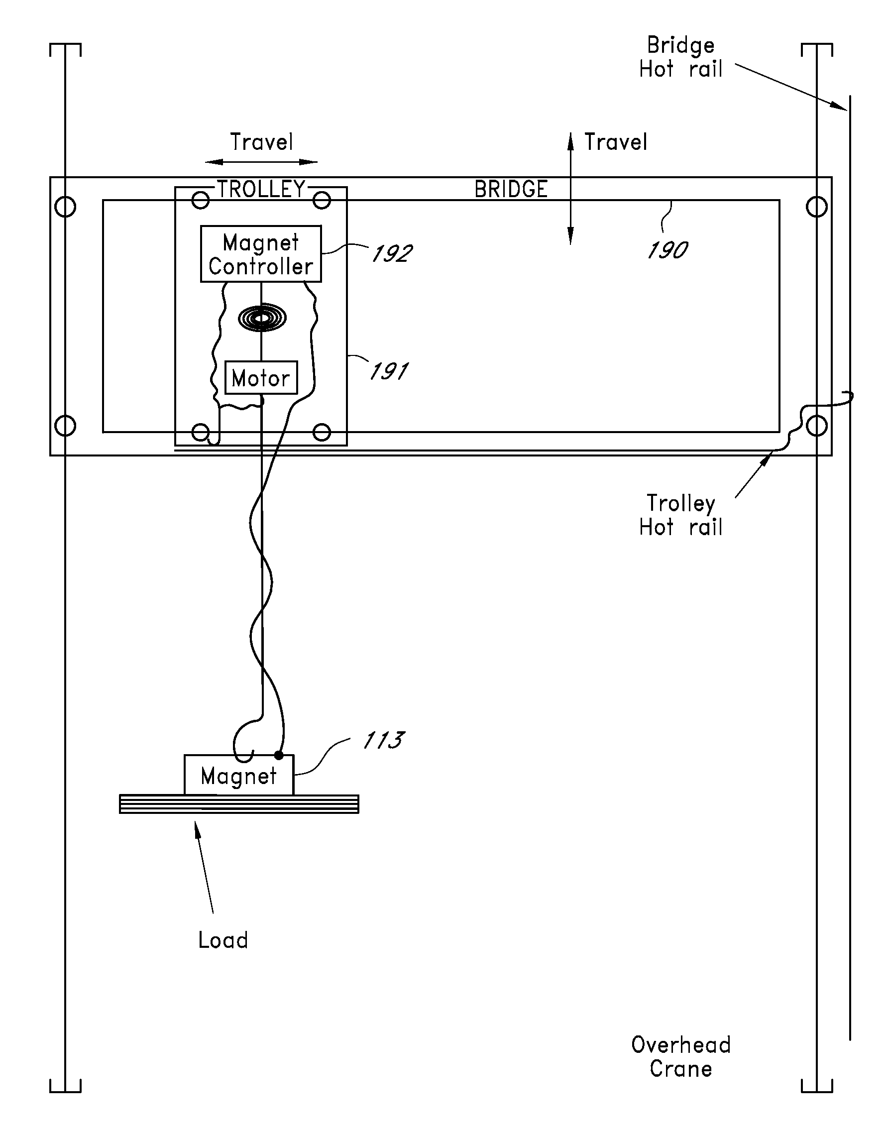
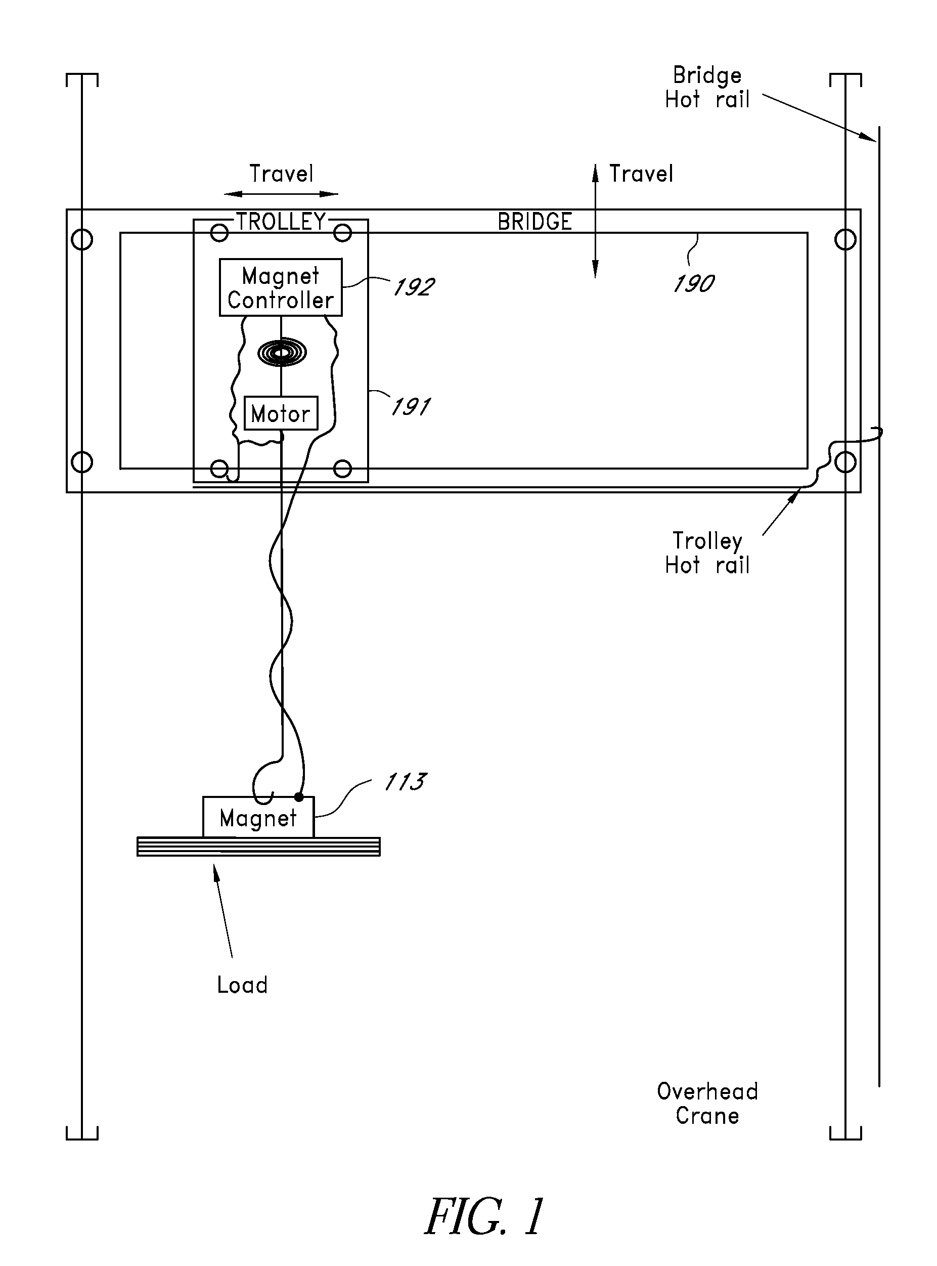
[0049]FIG. 1 shows an overhead crane with a bridge 190 provided to a trolley 191. The trolley 191 is provided to a lifting magnet 113 controlled by a magnet controller 192. The lifting magnet 113 is attached by cables to the magnet controller 192 which controls the lifting magnet 113. The lifting magnet 113 is used to lift ferromagnetic materials such as, for example, one or more steel plates, steel girders, scrap steel, etc.

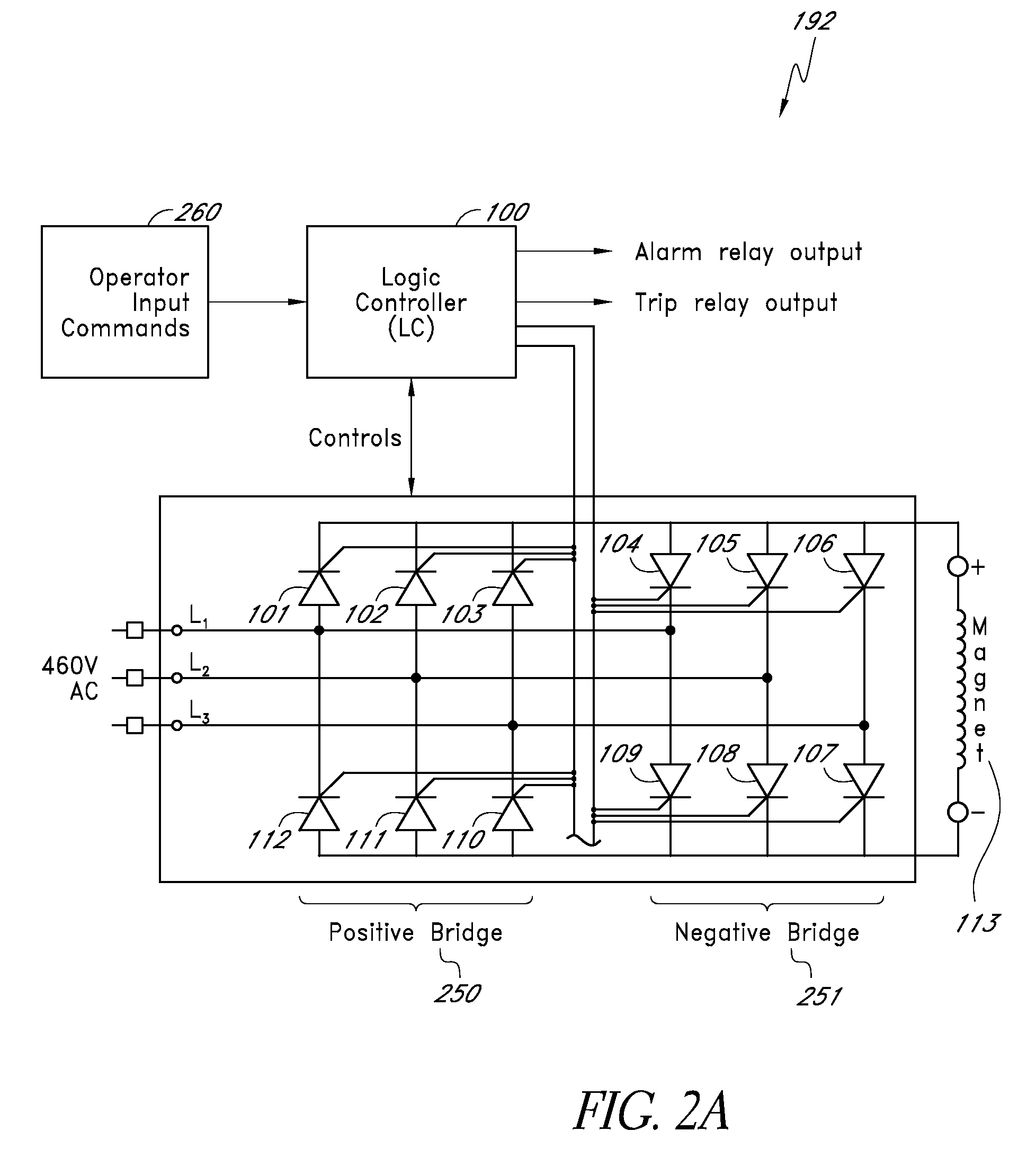
[0050]FIG. 2 shows a lifting magnet controller circuit 192 that includes a Logic Controller (LC) 100. In one embodiment, the LC 100 can be a Programmable Logic Controller (PLC). The LC 100 receives input commands from an operator console 260 and provides alarm and trip relay outputs. The operator console 260 can be configured as a computer with a display and human interface devices (e.g., mouse, keyboard, touchscreen, etc.). Outputs from the logic controller 100 are provided to respective switches 101-112. The switches 101-103 and 110-112 are configured in a pos...


PUM

PropertyMeasurementUnit
temperatureaaaaaaaaaa
voltageaaaaaaaaaa
DC voltageaaaaaaaaaa

Abstract

A magnet controller supplied by an AC source controls a lifting magnet. Two bridges allow DC current to flow in both directions in the lifting magnet. During “Lift”, relatively high voltage is applied to the lifting magnet until it reaches its cold current. Then voltage is lowered. After a desired interval, once the magnet has had time to build its electromagnetic field, voltage is further reduced to prevent the magnet from overheating. The magnet lifting forced is maintained due to the magnetic circuit hysteresis. During “Drop”, reverse voltage is applied briefly to demagnetize the lifting magnet. At the end of the “Lift” and the “Drop”, most of the lifting magnet energy is returned to the line source. A logic controller controls current and voltage of the magnet and calculates the magnet's temperature. In one embodiment, a “Sweep” switch is provided to allow reduction of the magnet power to prevent attraction to the bottom or walls of magnetic rail cars or containers.

Description

REFERENCE TO RELATED APPLICATIONS[0001]The present application is a continuation-in-part of claims priority from U.S. Application No. 61 / 066,121, filed Dec. 19, 2007, titled “METHOD FOR CONTROLLING A LIFTING MAGNET SUPPLIED WITH AN AC SOURCE,” and a continuation-in-part of claims priority from U.S. application Ser. No. 12 / 040,741, filed Feb. 29, 2008, titled “METHOD AND APPARATUS FOR CONTROLLING A LIFTING MAGNET SUPPLIED WITH AN AC SOURCE”, the entire contents of which is hereby incorporated by reference.BACKGROUND[0002]1. Field of the Invention[0003]The present invention relates to a method and apparatus for controlling a lifting magnet of a materials handling machine for which the source of electrical power is an AC power source.[0004]2. Prior Art[0005]Lifting magnets are commonly attached to hoists to load, unload, and otherwise move scrap steel and other ferrous metals. For many years, cranes were designed to be powered by DC sources, and therefore systems used to control liftin...

Claims


Application Information

Patent Timeline
Patent Type & Authority Applications(United States)
IPC IPC(8): H01F7/18
CPCB66C1/08H01F7/206H01F7/1811H01F7/18
Inventor MARAVAL, JEAN LAURENTTHOMPSON, ANTHONY RAY
Owner HUBBELL IND CONTROLS
Why Eureka
Try Eureka