
Programmable Logic Controller And Camera Input Expansion Unit

Active Publication Date: 2020-08-13
KEYENCE
View PDF0 Cites 4 Cited by
  • Summary
  • Abstract
  • Description
  • Claims
  • Application Information

AI Technical Summary

Benefits of technology

The invention is about a programmable logic controller and a camera input expansion unit that can connect to a device and synchronize their timing. This helps to capture accurate information about the device.

Problems solved by technology

However, if a difference exists between the time of acquisition of device value in the PLC and the time of acquisition of camera image, the diagnosis of the trouble will take time and manpower.
On the other hand, there is a problem that the both times cannot be easily synchronized with each other because of communication delay.

Method used


Image

  • Programmable Logic Controller And Camera Input Expansion Unit
  • Programmable Logic Controller And Camera Input Expansion Unit
  • Programmable Logic Controller And Camera Input Expansion Unit

Examples


Embodiment Construction

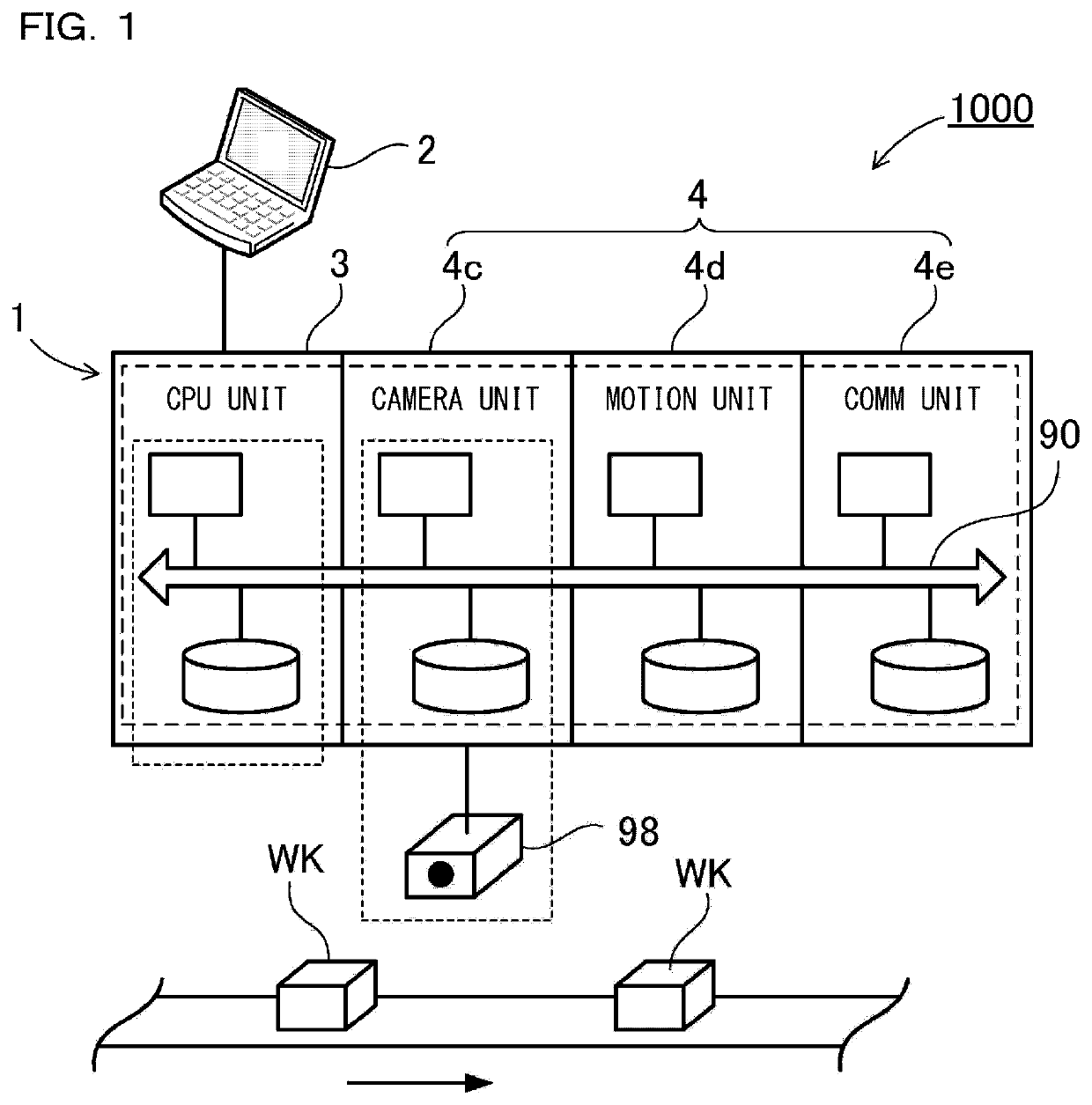
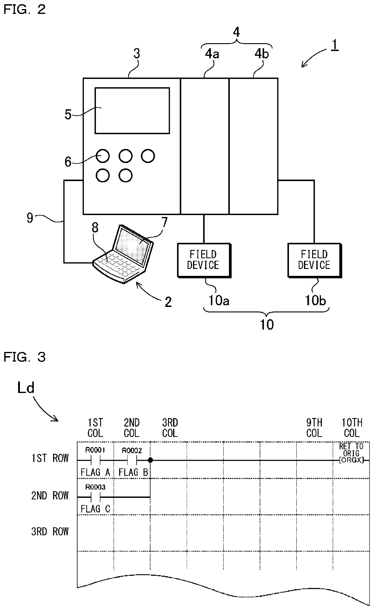
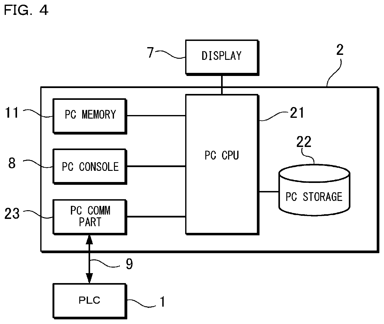
[0042]The embodiments will now be described with reference to the accompanying drawings, wherein like reference numerals designate corresponding or identical elements throughout the various drawings. It should be appreciated, however, that the embodiments described below are illustrations of a programmable logic controller and a camera input expansion unit to give a concrete form to technical ideas of the invention, and a programmable logic controller and a camera input expansion unit of the invention are not specifically limited to description below. Furthermore, it should be appreciated that the members shown in claims attached hereto are not specifically limited to members in the embodiments. Unless otherwise specified, any dimensions, materials, shapes and relative arrangements of the parts described in the embodiments are given as an example and not as a limitation. Additionally, the sizes and the positional relationships of the members in each of drawings are occasionally show...


PUM


Abstract

A camera input expansion unit includes a camera-setting-information storage, a camera expansion processor, an image-recorder, and an image capture interface. The camera-setting-information storage stores setting information on the camera including the conditions of the image capture trigger. The camera expansion processor generates an ON / OFF signal for defining the image capture trigger based on the setting information of the camera. Based on the ON / OFF signal as the image capture trigger, the camera expansion processor acquires the image data which is generated by the camera. The image-recorder records the image data acquired by the camera expansion processor. The image capture interface is provided between the camera expansion processor and the camera. The image capture interface has an image-capture-trigger line propagating the ON / OFF signal to the camera and an image communication line propagating the image data generated by the camera to the camera expansion processor.

Description

CROSS-REFERENCE TO RELATED APPLICATIONS[0001]The present application claims priority under 35 U.S.C. § 119 to Japanese Patent Application No. 2019-023,076, filed on Feb. 12, 2019, the content of which is incorporated herein by reference in their entirety.BACKGROUND OF THE INVENTION1. Field of the Invention[0002]The present invention relates to a programmable logic controller and a camera input expansion unit.2. Description of the Related Art[0003]Programmable logic controllers (hereinafter also referred to as “PLCs” are controllers for controlling manufacturing equipment, conveying devices, and inspection devices in factory automation (FA). PLCs execute user programs (e.g., ladder programs) written by users whereby controlling various types of expansion units and to-be-controlled equipment. When a user actually runs his / her user program on a PLC, the user sometimes finds an unexpected event, which is unexpected at the time of the user program writing. In this case, the user necessar...

Claims


Application Information

Patent Timeline
IPC IPC(8): H04N5/232G05B19/05H04L29/08
CPCH04L67/26G05B2219/163G05B19/056H04N5/23222G05B19/05H04N23/617H04L67/55H04N23/64
Inventor TSUJIKAWA, RYOSUKE
Owner KEYENCE
Learn More