Circuit device, oscillator, electronic apparatus, and vehicle

a technology of circuit devices and electronic devices, applied in the direction of measurement devices, automatic control, instruments, etc., can solve the problem of phase difference between the oscillation signal output from the terminal and the oscillation signal outpu

Active Publication Date: 2017-10-26
SEIKO EPSON CORP
View PDF7 Cites 9 Cited by
  • Summary
  • Abstract
  • Description
  • Claims
  • Application Information

AI Technical Summary

Benefits of technology

[0009]With this configuration, one of offset adjustment data for GPS and offset adjustment data for UTC is set in the second register, and thus a phase difference between the reference signal and the oscillation signal can be set to a desired value corresponding to the type of reference signal. Offset adjustment data for adjusting a phase difference between the reference signal and the oscillation signal is set in the third register, and thus a phase difference between the reference signal and the oscillation signal can be set to any desired value. The first register stores phase comparison result data as the monitor data, and thus the monitor data can be output to an external device. Consequently, it is possible to test an operation of a PLL circuit.
[0017]There is a time difference between a GPS time pulse and a UTC time pulse. According to the present embodiment, offset adjustment data for GPS and offset adjustment data for UTC which are different from each other are set, and thus a phase difference corresponding to the time difference can be intentionally added to the oscillation signal. Consequently, it is possible to perform accurate time synchronization even in a case where either of the GPS time pulse and the UTC time pulse is used as the reference signal.
[0019]As mentioned above, if offset adjustment data for GPS corresponding to a predetermined value for GPS and offset adjustment data for UTC corresponding to a predetermined value for UTC are set, it is possible to perform accurate time synchronization even in a case where either of a GPS time pulse and a UTC time pulse is used as the reference signal.
[0021]According to the aspect of the invention, the phase comparator performs phase comparison of comparing a count value in the counter with an expected value in integers, and thus the phase comparator can be formed with a simple configuration. Consequently, it is possible to miniaturize the circuit device. According to the aspect of the invention, the phase comparator compares a count value in the counter in n cycles of the reference signal with the expected value of the count value in integers. In addition, n can be set to 2 or more. Consequently, the time resolution of a phase error detected by the phase comparator can be reduced. In other words, it is possible to reduce a phase error in a lock state of a PLL circuit including the phase comparator.

Problems solved by technology

For example, there is a probability that a phase difference may occur between the oscillation signal output from the terminal of the circuit device and the reference signal due to delay or the like in a feedback path to the phase comparator from the oscillation signal generation circuit.

Method used


Image

  • Circuit device, oscillator, electronic apparatus, and vehicle
  • Circuit device, oscillator, electronic apparatus, and vehicle
  • Circuit device, oscillator, electronic apparatus, and vehicle

Examples


modification examples

11. Modification Examples

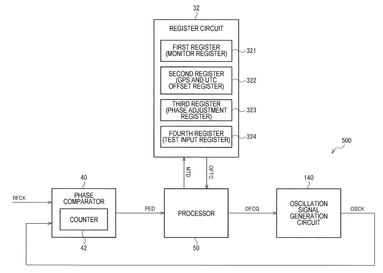
[0224]Next, various modification examples of the present embodiment will be described. FIG. 19 illustrates a configuration example of a circuit device according to a modification example of the present embodiment.

[0225]In FIG. 19, the D / A converter 80 is not provided in the oscillation signal generation circuit 140 unlike in FIG. 8. An oscillation frequency of the oscillation signal OSCK generated by the oscillation signal generation circuit 140 is directly controlled on the basis of the frequency control data DFCQ from the processor 50. In other words, an oscillation frequency of the oscillation signal OSCK is controlled without using the D / A converter.

[0226]For example, in FIG. 19, the oscillation signal generation circuit 140 has a variable capacitance circuit 142 and an oscillation circuit 150. The variable capacitance circuit 142 is provided instead of the variable capacitance capacitor CX1 illustrated in FIG. 18, and one end of the variable capacitance...


PUM


Abstract

A circuit device includes a phase comparator that performs phase comparison between an input signal based on an oscillation signal and a reference signal, a processor that performs a signal process, and an oscillation signal generation circuit that generates the oscillation signal having an oscillation frequency which is set on the basis of frequency control data from the processor. The circuit device also includes at least one of a first register that stores phase comparison result data, a second register in which one of offset adjustment data for GPS and offset adjustment data for UTC is set, and a third register in which offset adjustment data for adjusting a phase difference is set.

Description

CROSS-REFERENCE TO RELATED APPLICATIONS[0001]The present application claims priority to Japanese Patent Application JP 2016-086657, filed Apr. 25, 2016, the entire disclosure of which is hereby incorporated by reference herein.BACKGROUND1. Technical Field[0002]Various embodiments of the present invention relates to a circuit device, an oscillator, an electronic apparatus, and a vehicle.2. Related Art[0003]In the related art, there is an oscillator such as an oven controlled crystal oscillator (OCXO) or a temperature compensated crystal oscillator (TCXO). For example, in a base station, a network router, a measurement apparatus, and the like using such an oscillator as a reference signal source, a phase locked loop (PLL) circuit including the oscillator is configured, and an oscillation signal of the oscillator is synchronized with a reference signal such as a GPS signal.[0004]The related art of the PLL circuit is disclosed in, for example, JP-A-2009-268047. In JP-A-2009-268047, a ph...

Claims


Application Information

Patent Timeline
Patent Type & Authority Applications(United States)
IPC IPC(8): G01S19/23H03L1/04H03L7/093H03L7/095H03L7/099
CPCG01S19/235H03L7/095H03L7/099H03L1/04H03L7/093H03L7/07H03L7/081H03L7/085H03L7/104H03L1/022H03L1/028H03L7/1075
Inventor NAKAJIMA, KATSUHITOSEO, KENTARO
Owner SEIKO EPSON CORP
Why Eureka
Try Eureka