Communication system and time synchronization method
a communication system and time synchronization technology, applied in the field of communication system and time synchronization method, can solve the problem that the precision of time synchronization cannot be sufficiently enhanced in the above general method, and achieve the effect of accurate time synchronization
- Summary
- Abstract
- Description
- Claims
- Application Information
AI Technical Summary
Benefits of technology
Problems solved by technology
Method used
Image
Examples
embodiment 1
1. Embodiment 1
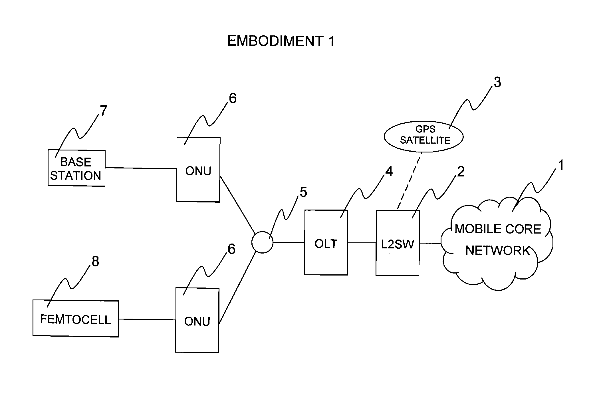
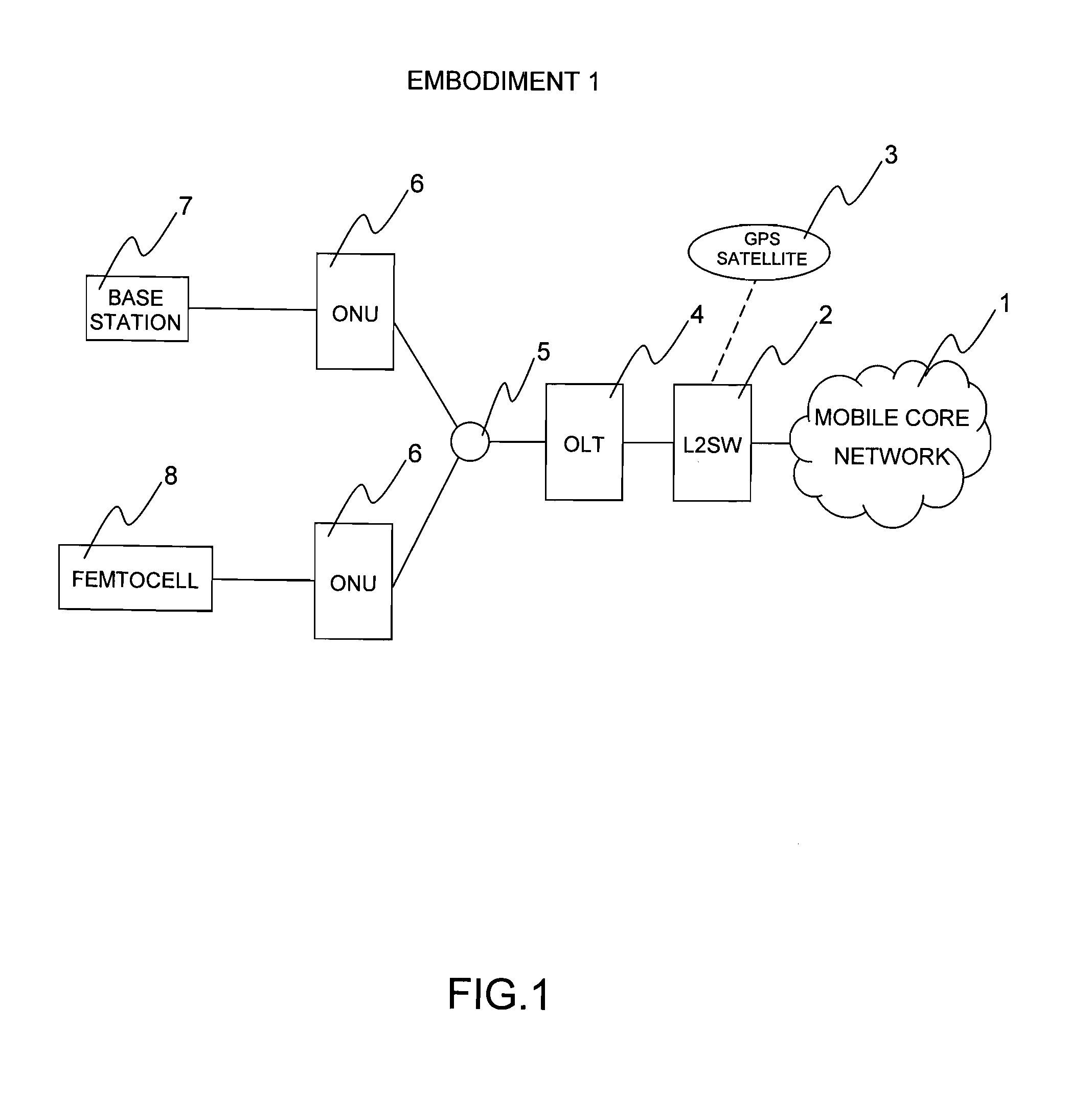
[0066]FIG. 1 illustrates a system configuration diagram of an embodiment 1 of the present invention. The system includes a mobile core network 1 that is a communication network of cellular phones, and an L2SW 2 as an interface for communicating with the mobile core network 1, and the L2SW 2 has a function of receiving a GPS signal from a GPS satellite 3. The L2SW 2 accommodates an OLT 4, and the OLT 4 can accommodate plural ONUs 6 with the use of an optical splitter 5. Each of the ONUs 6 accommodates a base station 7 or a femtocell 8 therein. Now, a description will be given of a method of realizing time synchronization with provision of a time synchronization function in the OLT 4 at a master side and without provision of a GPS signal receiver by the base station 7 or the femtocell 8 at a slave side.
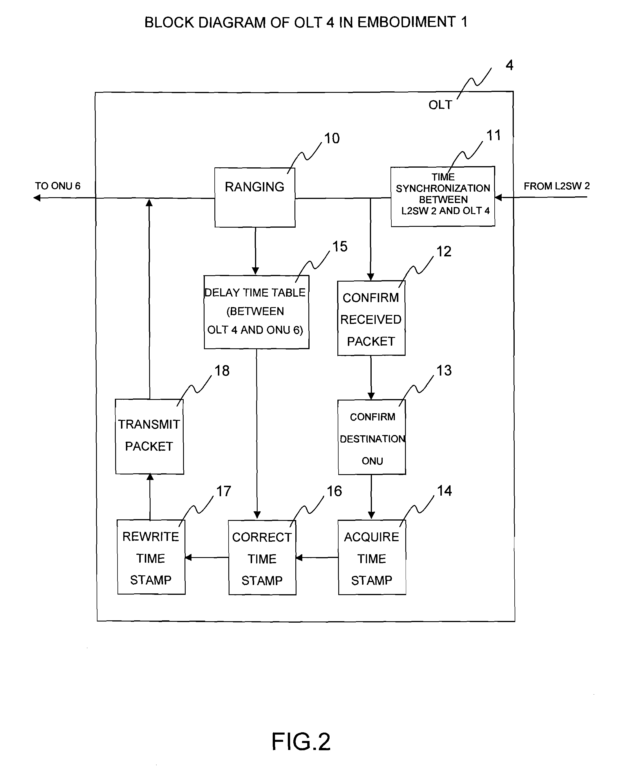
[0067]FIG. 2 is a functional block diagram of the OLT 4 in the embodiment 1 of the present invention. The OLT 4 periodically conducts a distance measurement (ranging) bet...
embodiment 2
2. Embodiment 2
2-1. Embodiment 2-1
[0077]Subsequently, an embodiment 2 of the present invention will be described. The configuration of the device and the block diagram are identical with those in the embodiment 1. In this embodiment, a method of realizing the time synchronization with higher precision than that in the embodiment 1 will be described.
[0078]FIG. 6 illustrates a time synchronization sequence according to the embodiment 2-1. In the embodiment 1, an error of 0.01 microseconds occurs in the clock timer values of the L2SW 2 and the base station 7. This is particularly because there is no function of correcting the propagation time between the ONU 6 and the base station 7. In a sequence diagram of the embodiment 2-1, the base station 7 transmits a delay measurement signal 109 toward the ONU 6, and the ONU 6 returns a delay measurement signal 110 to the base station 7, thereby measuring the round-trip propagation delay time between the base station 7 and the ONU 6 to obtain t...
embodiment 2-2
2-2. Embodiment 2-2
[0079]FIG. 7 illustrates a block diagram of the ONU 6 according to an embodiment 2-2. The ONU 6 receives, through ranging processing (30), information on the delay time between the OLT 4 and the ONU 6 and the delay time between the L2SW 2 and the OLT 4, which have been measured by the OLT 4, from the OLT 4, and stores the information in a delay time table (31). On the other hand, upon receiving the delay measurement signal from the base station 7 (32), the ONU 6 confirms a received packet (33), acquires the time stamp (34), refers to the delay time table (31), and returns the delay measurement signal to the base station 7 (36) after a time of twice the stored total delay time between the L2SW 2 and the ONU 6 (35). The base station 7 calculates a value of the propagation delay from the receive time of the delay measurement signal so as to conduct the time synchronization.
[0080]FIG. 8 illustrates a time synchronization sequence according to the embodiment 2-2. In th...
PUM
 Abstract
Description
Claims
Application Information
 - R&D
- Intellectual Property
- Life Sciences
- Materials
- Tech Scout
- Unparalleled Data Quality
- Higher Quality Content
- 60% Fewer Hallucinations
Browse by: Latest US Patents, China's latest patents, Technical Efficacy Thesaurus, Application Domain, Technology Topic, Popular Technical Reports.
© 2025 PatSnap. All rights reserved.Legal|Privacy policy|Modern Slavery Act Transparency Statement|Sitemap|About US| Contact US: help@patsnap.com


