Method and system for time synchronisation in a distributed communications network

ime synchronisation technology, applied in the field of method and system for time synchronisation in a distributed communications network, can solve the problems of high cost, probability delay, and inability to accurately and precisely measure the time synchronisation data transfer, and achieve the effect of efficient network and precise and exact manner

Inactive Publication Date: 2006-05-25
NOKIA SIEMENS NETWORKS GMBH & CO KG
View PDF6 Cites 10 Cited by
  • Summary
  • Abstract
  • Description
  • Claims
  • Application Information

AI Technical Summary

Benefits of technology

[0006] Another solution is to modify the transport infrastructure (transport circuitry) of the system in order to reduce the variabilities of transfer times. This can be achieved for example in modifying the transport infrastructure to emulate a Time Division Multiple Access (TDMA) like operation which generates circuit-switched like connections between nodes with a constant transfer delay. Or in another example, by modifying the transport infrastructure in a way that traffic priorities can be assigned to the data being carried over the network. In this way, time synchronisation data is assigned the highest traffic priority and consequently such time synchronisation data will always be transmitted ahead of other lower priority traffic data which is pre-empted, thus ensuring a constant transfer delay.
[0010] In view of the drawbacks that exist in the prior art, an objective of the present invention is to identify a method, a system and a node that can provide a more precise time synchronisation in today's networking environment without having to resort to technically complex and costly modifications of the transport infrastructure of systems that are currently available.
[0022] Thus the above method, system and node are advantageous as they provide great benefits in a networking environment, in allowing for distributed network nodes to maintain their local clocks synchronised with a central clock, in a precise and exact manner.
[0023] Further optional advantages can be seen in the dependent claims, where the synchronisation messages transmitted have the same length and the same data rate in order to ensure that the transmission times of the synchronisation messages are constant. Additionally, delays experienced by the synchronisation messages are detected and are used in determining whether the clock synchronisation procedure is to be performed or terminated, ensuring an efficient procedure. Furthermore, these delays can be determined either as time values corresponding to the experienced delays or as indicators indicating that a delay occurred, allowing for a versatile clock synchronisation procedure. A yet another advantage of this invention is that a comparison between the values of calculated round trip times is performed and if a variance is detected, feedback to a network management centre is provided in the form of an alarm message, allowing for troubleshooting to be performed, thus maintaining an efficient network.

Problems solved by technology

Time synchronisation of distributed network nodes that are connected in a hub configuration to a global (master) clock through a shared off-the-shelf commercial switch, for example over a Gigabit (Gbit) Ethernet switch, is not precise enough, because the variability of transfer times between the involved elements is too high.
This variability is caused by other traffic that is carried in the system which in turn causes delays to the time synchronisation data being transferred in a probabilistic fashion.
However, such a solution has a major drawback in that it is relatively expensive to implement and would mean that a higher initial investment would be necessary to build a network.

Method used


Image

  • Method and system for time synchronisation in a distributed communications network
  • Method and system for time synchronisation in a distributed communications network
  • Method and system for time synchronisation in a distributed communications network

Examples


Embodiment Construction

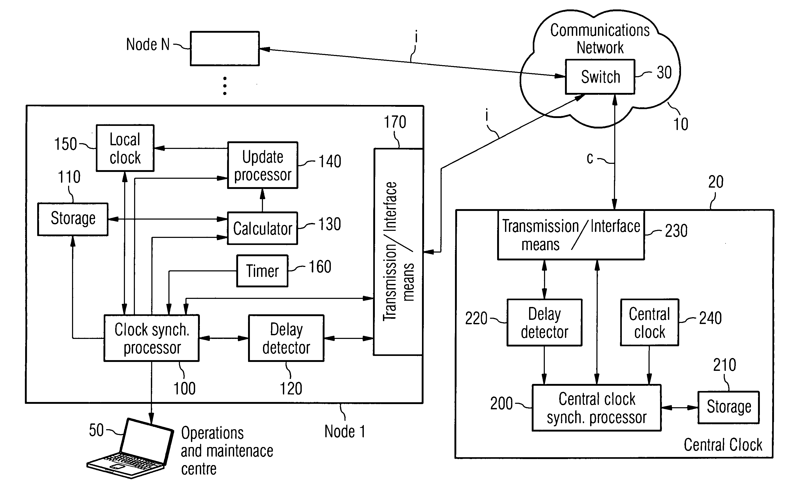
[0028] As can be seen in FIG. 1, a typical distributed network consists of N nodes, e.g, node 1, . . . node N, that are connected to a central clock 20 and to other destinations through a switch 30. The terms “global clock”, “master clock”, “central clock” are synonymous and well known in the art. Each one of the N nodes 1, . . . N has a local clock 150 that requires time synchronisation with the more precise central clock. In order for this to be achieved, each node will communicate with the central clock via the switch 30. As it can be seen from FIG. 1, the central clock is connected to the switch through a dedicated link thus ensuring that only a small amount of traffic is carried on this link.

[0029] Each node, as can be seen in FIG. 1, comprises of a clock synchronisation processor 100 which executes the procedure from the side of the node, storage means 110 for storing the different time values necessary for performing the synchronisation procedure, a delay detector 120 for de...


PUM


Abstract

Method, system and node for providing time synchronisation between local clocks located in nodes within a network and a central clock. The central clock and the nodes exchange messages. The messages transmitted contain a time stamp indicating the time of transmission. When messages are received, the time of reception is also determined. Based upon the calculation of the elapsed time taken by messages to be transmitted and received, a time difference can be estimated which indicates how much the clock on a node lags behind the central clock. Once this lag is known, the clock on the node can be updated. The proposed invention allows for a more precise time synchronisation to take place between nodes and a central clock without having to perform modifications on the transport circuitry of the system. The invention also allows for any changes in the network topology to be detected via any changes in the Round Trip Time, and a management centre to be notified in turn. Additionally, the invention allows for statistical information to be gathered in order to determine the quality of the synchronisation procedure.

Description

FIELD OF THE INVENTION [0001] The invention is used in communications networks where time synchronisation between a central clock and local clocks located on nodes distributed throughout the network is necessary. SUMMARY OF THE INVENTION [0002] Time synchronisation of distributed network nodes that are connected in a hub configuration to a global (master) clock through a shared off-the-shelf commercial switch, for example over a Gigabit (Gbit) Ethernet switch, is not precise enough, because the variability of transfer times between the involved elements is too high. This variability is caused by other traffic that is carried in the system which in turn causes delays to the time synchronisation data being transferred in a probabilistic fashion. [0003] In order to overcome this problem alternative solutions have been implemented. [0004] One such solution achieves precise time synchronisation by using dedicated infrastructure such as special circuits and dedicated links that are exclus...

Claims


Application Information

Patent Timeline
Patent Type & Authority Applications(United States)
IPC IPC(8): H04J3/06
CPCH04J3/0638H04J3/0682
Inventor SCHOPP, MICHAEL
Owner NOKIA SIEMENS NETWORKS GMBH & CO KG
Why Eureka
Try Eureka