Dispersion compensation device and method for high-accuracy optical fiber timing system

A dispersion compensation and timing system technology, applied in wavelength division multiplexing systems, optical multiplexing systems, transmission systems, etc., can solve problems such as inconsistent time delays

Inactive Publication Date: 2016-02-24
SOUTHWEST UNIVERSITY FOR NATIONALITIES
View PDF4 Cites 10 Cited by
  • Summary
  • Abstract
  • Description
  • Claims
  • Application Information

AI Technical Summary

Problems solved by technology

[0022] The present invention overcomes the deficiencies of the prior art, and provides a dispersion compensation device and method for a high-precision optical fiber timing syst

Method used


Image

  • Dispersion compensation device and method for high-accuracy optical fiber timing system
  • Dispersion compensation device and method for high-accuracy optical fiber timing system
  • Dispersion compensation device and method for high-accuracy optical fiber timing system

Examples


Embodiment Construction

[0080] The present invention will be further described in detail below in conjunction with examples, but the embodiments of the present invention are not limited thereto.

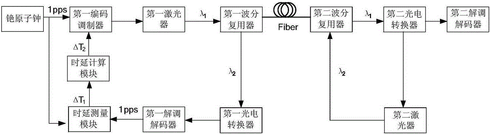
[0081] The working principle of the high-precision time-frequency transfer system based on wavelength division multiplexing technology is as follows: figure 1 shown. The system is mainly composed of a timing master station including the first wavelength division multiplexer and its left part, and a timing slave station including the second wavelength division multiplexer and its right part. Attached below figure 1 , the patent of the present invention is described in detail.

[0082] Such as figure 1 As shown, a dispersion compensation device for high-precision optical fiber timing system, it includes a timing master station and a timing slave station, and the timing master station includes:

[0083] The cesium atomic clock is used to output the pulse signal to the first code modulator;

[0084] a firs...


PUM

PropertyMeasurementUnit
Wavelengthaaaaaaaaaa

Abstract

The invention discloses a dispersion compensation device and method for a high-accuracy optical fiber timing system. The method comprises a step of measuring a sum deltaT1 of forward and backward transmission delays of two different wavelengths between a timing master station and a timing slave station receiving end. The step comprises the following sub-steps that: a pulse signal output by a cesium atomic clock is modulated into a radio frequency signal through a first encoding modulator on the timing master station; a first wavelength division multiplexer converts the radio frequency signal into an optical signal of which the wavelength is lambda1, and couples the optical signal into an optical fiber; after reception of the optical signal of which the wavelength is lambda1, a second photoelectric converter transmits the radio frequency signal to a second laser and a second demodulation decoder respectively; after reception of the radio frequency signal, the second laser converts the radio frequency signal into an optical signal of which the wavelength is lambda2; and lastly, a returned pulse signal and the pulse signal output by the cesium atomic clock are transmitted to a delay measurement module simultaneously in order to perform delay measurement, wherein a measurement result is the sum of the forward and backward transmission delays between the timing master station and the timing slave station receiving end. Through adoption of the device and method, all-optical network synchronization can be realized, and the timing accuracy is increased.

Description

technical field [0001] The invention belongs to the field of optical fiber communication, and mainly relates to a dispersion compensation device and method for a high-precision optical fiber timing system. Background technique [0002] Existing dispersion compensation schemes, in high-speed and large-capacity optical fiber communication systems, due to the nonlinearity of the optical fiber medium, the shape of the optical pulse envelope will change. This change that affects the reception of optical signals is called group velocity dispersion. Velocity dispersion will cause the broadening of optical signal transmission waveform. Although working at the zero-dispersion wavelength is desirable from the standpoint of preventing pulse broadening, there are other factors to consider in actual design. For example, in a wavelength division multiplexing (WDM) system, only one channel can be arranged at most at the zero-dispersion wavelength, and when the dispersion effect is small, ...

Claims


Application Information

Patent Timeline
IPC IPC(8): H04B10/2525H04J14/02
CPCH04B10/2525H04J14/0227
Inventor 黄勤珍彭良福苗峰
Owner SOUTHWEST UNIVERSITY FOR NATIONALITIES
Why Eureka
Try Eureka