Armrest structure for seat

Active Publication Date: 2020-08-20
STARTING IND CO LTD
View PDF0 Cites 0 Cited by
  • Summary
  • Abstract
  • Description
  • Claims
  • Application Information

AI Technical Summary

Benefits of technology

[0011]According to the aspect of the present disclosure, since the armrest can be moved in the lateral width direction with respect to the seat surface, an interval between the armrest on both sides can be adjusted in accordance with the physique and the posture of a seated person. Further, since the shaft member protruding in the lateral width direction from the backrest is not required to be used, the angle of the armrest does not change due to the reclining. In addition, since no protruding member is present, a degree of freedom in layout can be increased. Moreover, since the guide block is simply required be vertically overlapped with respect to the armrest, it is possible to change a position of the armrest in the lateral width direction without greatly changing the existing layout of the seat or the existing structure of the armrest.
[0012]According to another aspect of the present disclosure, the operation portion may include a screw shaft which is rotatable around an axis of the screw shaft. The guide block may be attached to the screw shaft. The guide block attached to the screw shaft may be configured to move in an axial directi

Problems solved by technology

In such armrest of related art, there is a problem that the armrest cannot be moved in a lateral width direction with respect to a seat surface, and thus cannot sufficiently adapt to the physique and the posture of an operator.
However, in the configuration described in JPH07-23461U, since the armrests are attached to the support shafts protruding from the backrest, there is a problem that angles of the armrests change due to reclining of the backrest.
In addition, since support shafts protruding in the lateral width direction are required, there is a problem that a layout of the

Method used


Image

  • Armrest structure for seat
  • Armrest structure for seat
  • Armrest structure for seat

Examples


Example

[0021]An embodiment of the present disclosure will be described with reference to the drawings.

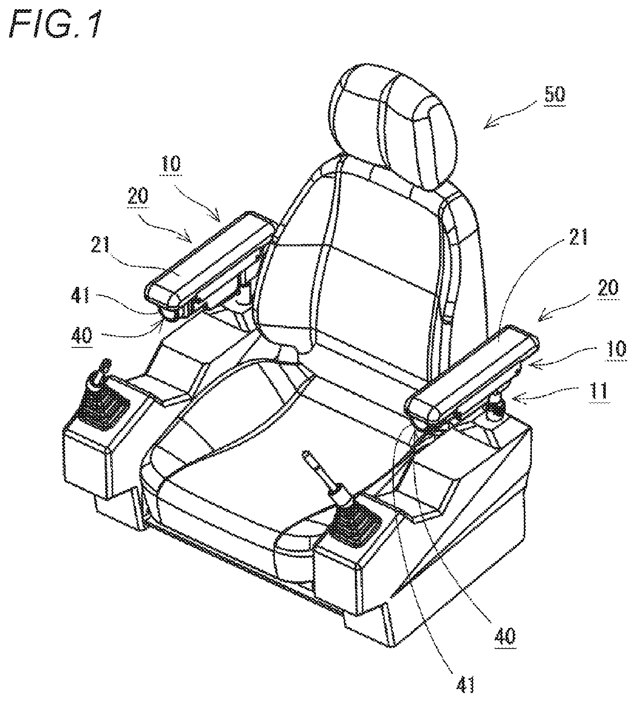
[0022]Armrest structures 10 according to the present embodiment are installed on a seat 50 such as a driver seat of a construction machine, and are disposed on both sides of the seat 50, for example, as shown in FIG. 1. Each of the armrest structures 10 includes a support portion 11, an armrest 20, a guide block 30, and an operation portion 40.

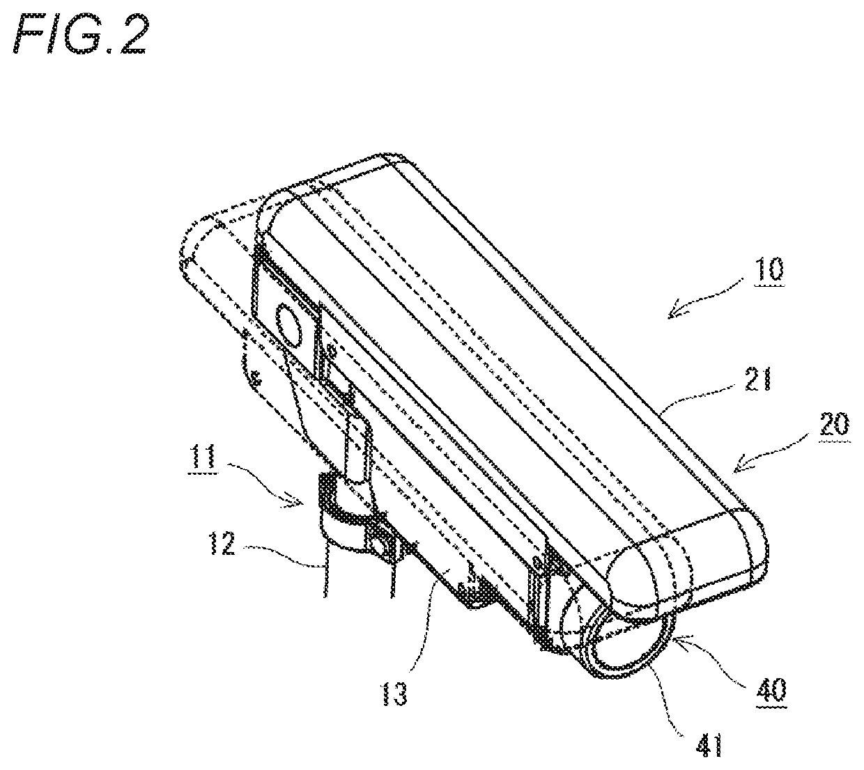
[0023]The support portion 11 supports the armrest structure 10. The support portion 11 is disposed on a side portion of the seat 50, and an armrest 20 is attached to an upper portion of the support portion 11. As shown in FIG. 2, the support portion 11 according to the present embodiment includes a support column 12 and a support arm portion 13.

[0024]The support column 12 is a pipe erected on the side portion of the seat 50. The support column 12 according to the present embodiment is attached to the seat 50 so as to be extendable, and can be fixed i...


PUM


Abstract

An armrest structure for seat includes an armrest configured to move in a lateral width direction of the seat, a guide block configured to move in a front-rear direction of the seat, and an operation portion configured to be manually operated, such that the guide block moves in the front-rear direction. The armrest and the guide block are slidably engaged with each other in a direction inclined with respect to the lateral width direction and the front-rear direction of the seat. The armrest is configured to move in conjunction with the guide block in the lateral width direction, in response to an operation that the operation portion is operated to move the guide block in the front-rear direction. According to this armrest structure, an interval between the armrest on both sides can be adjusted in accordance with the physique and the posture of a seated person.

Description

CROSS-REFERENCE TO RELATED APPLICATIONS[0001]This application is based on and claims priority under 35 USC 119 from Japanese Patent Application No. 2019-026214 filed on Feb. 18, 2019, the contents of which are incorporated herein by reference.TECHNICAL FIELD[0002]The present disclosure relates to an armrest structure used in a driver seat of a construction machine.BACKGROUND ART[0003]In general, armrests are provided on both sides of a driver seat of a construction machine such as an excavator. As such armrest, for example, there has been an armrest whose upper-lower height position can be adjusted as shown in JPH11-293702A.[0004]In such armrest of related art, there is a problem that the armrest cannot be moved in a lateral width direction with respect to a seat surface, and thus cannot sufficiently adapt to the physique and the posture of an operator.[0005]In this regard, JPH07-23461U (see FIG. 8 and the like) describes a structure including two support shafts protruding in a late...

Claims


Application Information

Patent Timeline
IPC IPC(8): B60N2/75B60N2/38
CPCB60N2/773B60N2/38B60N2/777
Inventor ISHIMIZU, AMIKATO, HIROKI
Owner STARTING IND CO LTD
Why Eureka
Try Eureka