Compressor housing for turbocharger and method for manufacturing the same

a compressor housing and turbocharger technology, applied in the direction of machines/engines, mechanical equipment, liquid fuel engines, etc., can solve the problems of reducing the compression efficiency of supplied air, increasing manufacturing costs, and reducing the workability of assembling, so as to reduce the parts count, improve the workability, and improve the effect of assembling

Inactive Publication Date: 2020-08-20
OTICS CORP
View PDF0 Cites 1 Cited by
  • Summary
  • Abstract
  • Description
  • Claims
  • Application Information

AI Technical Summary

Benefits of technology

[0028]According to the compressor housing for a turbocharger as the one embodiment of the present disclosure, the compressor housing for a turbocharger is dividably formed, and the refrigerant flow path is defined by the first flow-path formation part and the second flow-path formation part. The first flow-path formation part and the second flow-path formation part are formed respectively at each opposing part of the scroll piece and the shroud piece which oppose each other. The refrigerant flow path is sealed at an inner circumferential seal part on the inner circumferential side of the refrigerant flow path and at an outer circumferential seal part on the outer circumferential side of the refrigerant flow path. The inner circumferential seal part is formed by press-fitting the first press-fitting portion of the shroud piece into the first press-fitted portion of the scroll piece, and the outer circumferential seal part is formed by press-fitting the second press-fitting portion of the shroud piece into a second press-fitted portion of the scroll piece. The recirculation chamber of the recirculation part is formed of a space that is defined by a first recirculation chamber formation part of the scroll piece and a second recirculation chamber formation part of the shroud piece. The first recirculation chamber formation part and the second recirculation chamber formation part are formed respectively at each opposing part of the scroll piece and the shroud piece which oppose each other. Such configurations make it possible to seal the refrigerant flow path on the inner circumferential side of the refrigerant flow path and on the outer circumferential side of the refrigerant flow path while forming the recirculation part only by press-fitting the shroud piece into the scroll piece to assemble the both. Consequently, it becomes unnecessary to interpose an O-ring between the first flow-path formation part and the second flow-path formation part, and the assembling workability is satisfactory. Further, because the O-ring itself is not necessary, reduction of the parts count can be achieved. In addition, the refrigerant flow path provided in the compressor housing for a turbocharger makes it possible to restrain deposit accumulation in the diffuser passage to thereby achieve high supercharging on the high airflow-rate side of the compressor (at high speed rotation side of an engine) and to increase the maximum output of the engine.
[0029]In addition, the recirculation part can recirculate part of the air that has reached the shroud part, to an upstream side of the compressor impeller, and constitutes a so-called casing treatment. Accordingly, even when the flow rate of the compressor impeller is made largely increased in response to high supercharging, the operation range on the low airflow-rate side can be maintained and reduction of the low-speed torque can be prevented. In other words, the compressor housing for a turbocharger makes it possible both to maintain the low-speed torque, which is owing to the fact that the operation range on the low airflow-rate side is maintained by the recirculation part, and to increase the maximum output, which is owing to the fact that the refrigerant flow path brings about high supercharging.
[0030]Further, the compressor housing for a turbocharger is dividably formed and includes the scroll piece and the shroud piece. The scroll chamber is formed by assembling at least both the pieces to each other. Such a configuration makes it possible to form the scroll chamber with a circular cross section while forming the scroll chamber formation part in a shape having no undercut part, which enables mold releasing. As a result, the scroll chamber can be more easily formed by die casting while the compression efficiency for the supplied air can be improved.
[0031]As mentioned above, the one embodiment of the present disclosure can provide a compressor housing for a turbocharger in which sticking of deposit is prevented, satisfactory assembling workability is achieved, molding can be easily made by die casting, and high supercharging is achieved at low cost.
[0032]It is noted that the reference numerals throughout the specification correspond with the specific means which are described in the embodiments described later, and are not to limit the technical scope of the present disclosure.

Problems solved by technology

Thus, parts count is indispensably increased, which causes increase in manufacturing cost and reduction in assembling workability.
The cross-sectional shape of the scroll chamber is far different from a circle form accordingly, and such a shape causes reduction in compression efficiency of supplied air.
On the other hand, this method requires long casting cycle, and needs a sand shakeout operation for removing the sand core and an inspection work for checking remaining casting sand.
Meanwhile, the increased flow rate of the compressor impeller and the unfavorable cross sectional shape of the scroll chamber cause reduction of low-speed torque in an engine.

Method used


Image

  • Compressor housing for turbocharger and method for manufacturing the same
  • Compressor housing for turbocharger and method for manufacturing the same
  • Compressor housing for turbocharger and method for manufacturing the same

Examples


embodiments

Embodiment 1

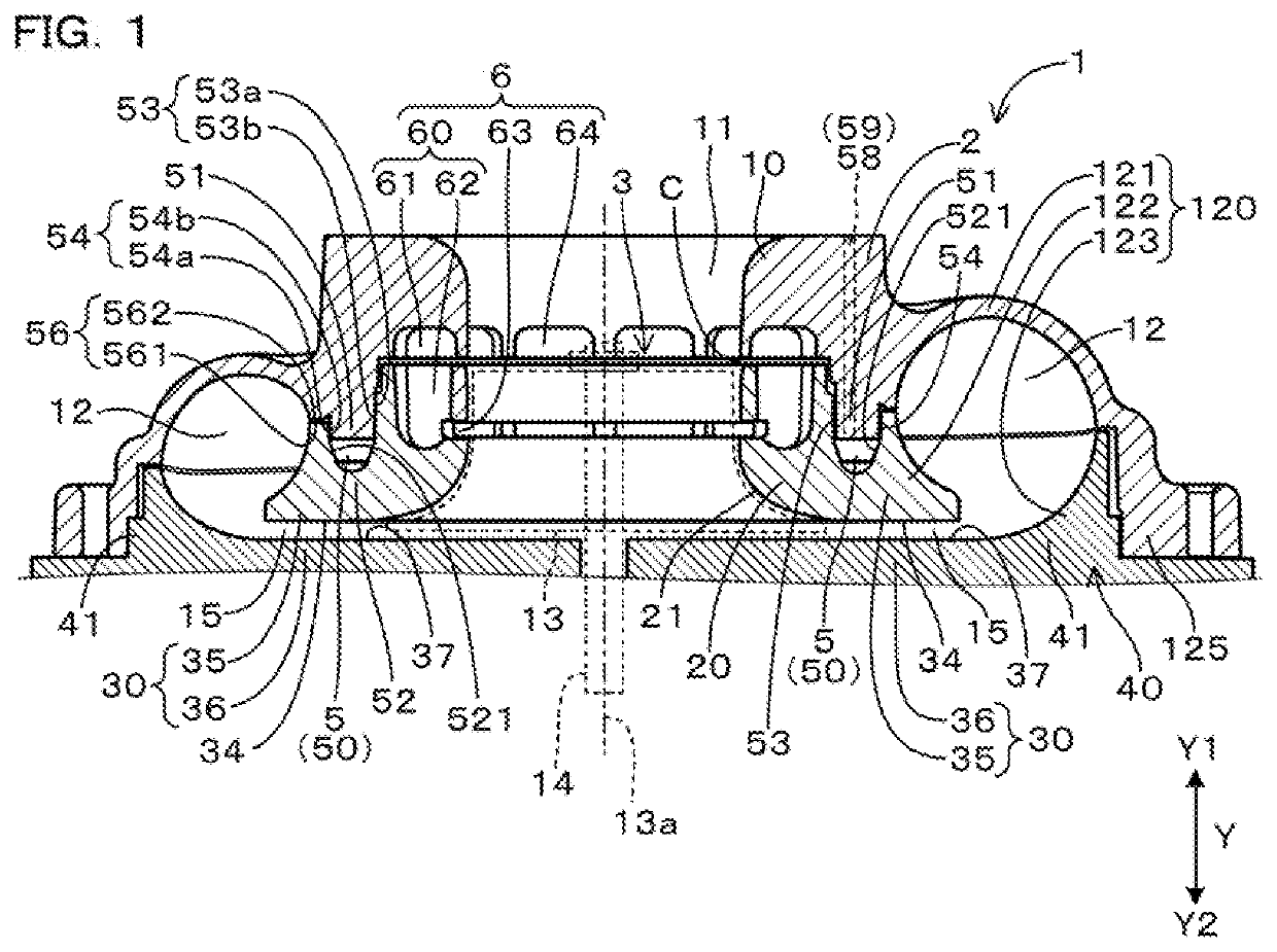
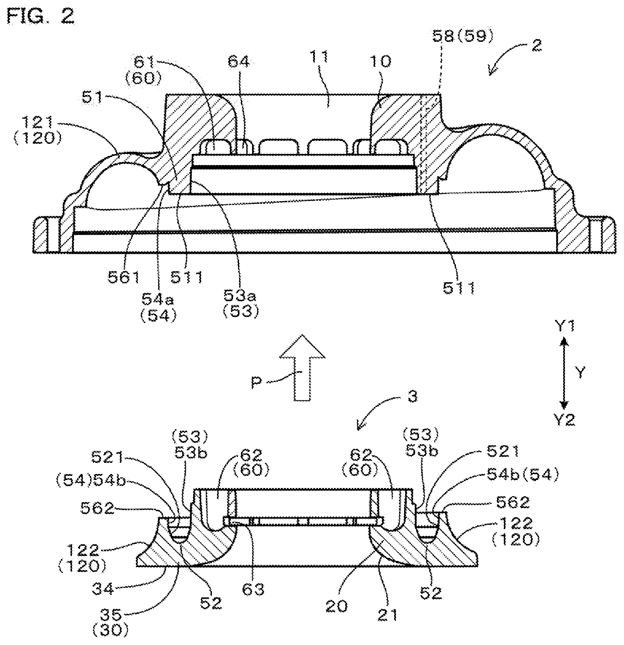
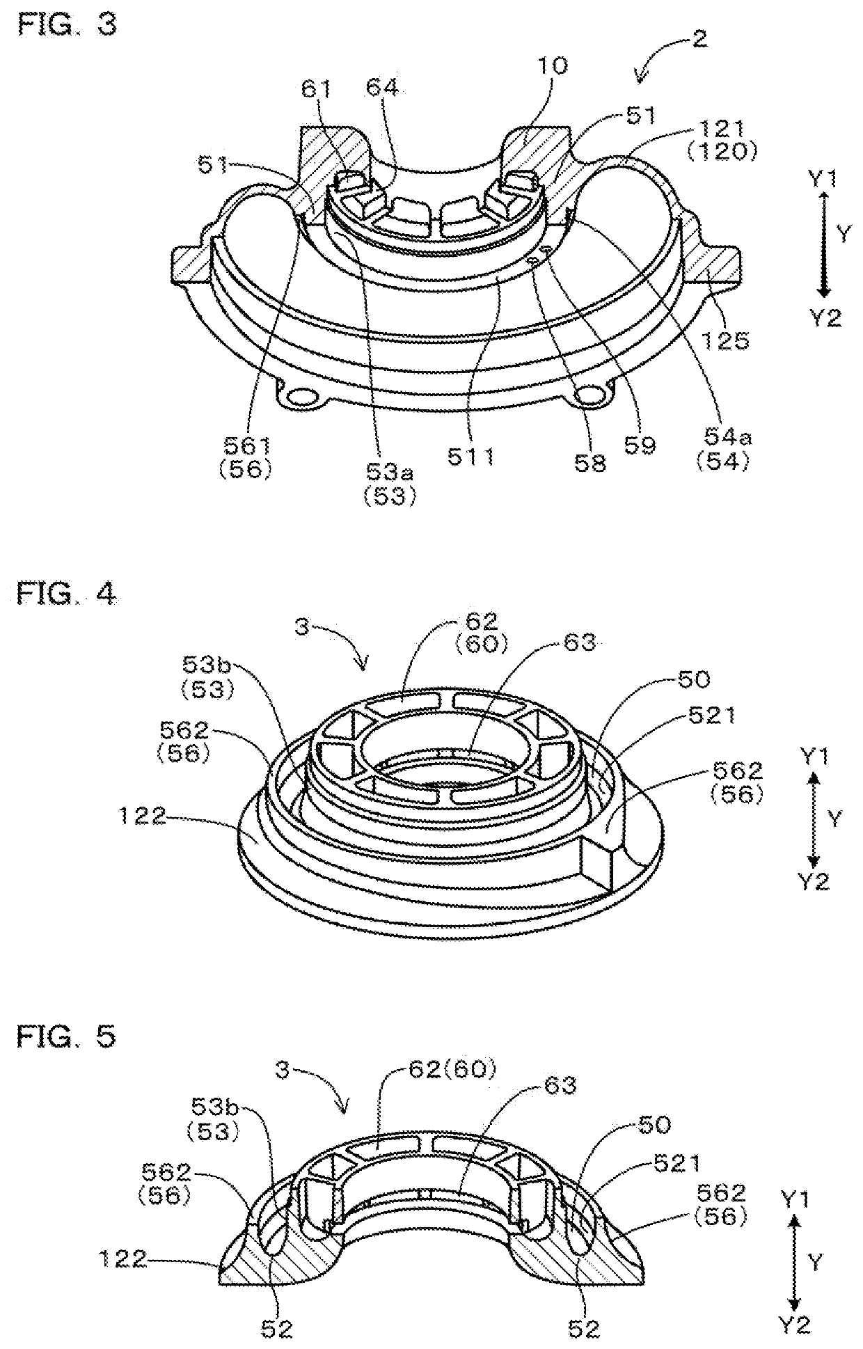
[0048]Hereinafter, embodiments of the aforementioned compressor housing for a turbocharger will be described with reference to FIGS. 1 to 7.

[0049]As shown in FIG. 1, a compressor housing 1 for a turbocharger houses a compressor impeller 13, and is provided with an intake port formation part 10, a shroud part 20, a diffuser part 30, a scroll chamber formation part 120, a refrigerant flow path 5, and a recirculation part 6.

[0050]The intake port formation part 10 forms an intake port 11 configured to suck in air toward the compressor impeller 13.

[0051]The shroud part 20 surrounds the compressor impeller 13 in the circumferential direction and has a shroud surface 21 facing the compressor impeller 13.

[0052]The diffuser part 30 is formed on the outer peripheral side of the compressor impeller 13 in the circumferential direction, and forms a diffuser passage 15 that allows compressed air discharged from the compressor impeller 13 to pass therethrough.

[0053]The scroll chamber f...


PUM


Abstract

A compressor housing for a turbocharger including a refrigerant flow path and a recirculation part, which is dividably composed of a scroll piece and a shroud piece. The refrigerant flow path is formed as an annular space that is defined by a first flow-path formation part of the scroll piece and a second flow-path formation part of the shroud piece that are fitted with each other. In the refrigerant flow path, a first press-fitting portion of the shroud piece is press-fitted into a first press-fitted portion of the scroll piece to form an inner circumferential seal part, and a second press-fitting portion of the shroud piece is press-fitted into a second press-fitted portion of the scroll piece to form an outer circumferential seal part. The recirculation part recirculates part of the air which has reached the shroud part to an upstream of the compressor impeller.

Description

CROSS-REFERENCE TO RELATED APPLICATION[0001]The present application claims priority under 35 U.S.C. § 119 to Japanese Application No. 2019-026413, filed on Feb. 18, 2019, entitled “COMPRESSOR HOUSING FOR TURBOCHARGER AND METHOD FOR MANUFACTURING THE SAME”. The contents of this application are incorporated herein by reference in their entirety.BACKGROUND OF THE INVENTIONField of the Invention[0002]The present disclosure relates to a compressor housing for a turbocharger and a method for manufacturing the same.Description of the Related Art[0003]A turbocharger to be mounted on an internal combustion engine of an automobile, etc. includes a compressor impeller and a turbine impeller, which are housed in a housing. The compressor impeller is disposed in an air flow path that is formed inside the housing. The air flow path is provided with an intake port for sucking in air toward the compressor impeller, a diffuser passage through which compressed air discharged from the compressor impel...

Claims


Application Information

Patent Timeline
Patent Type & Authority Applications(United States)
IPC IPC(8): F04D29/42F04D29/08F04D17/08
CPCF04D29/4206F04D29/083F04D17/08F04D29/441F04D29/582F04D29/624F04D29/023Y02T10/12
Inventor ISOGAI, TOMOYUKI
Owner OTICS CORP
Why Eureka
Try Eureka