Chain saw

A technology of chain saws and sprockets, which is applied in the field of chain saws, and can solve the problems that the maximum output of the motor cannot be fully ensured, the clutch device cannot work, and hinder the large-scale motor, so as to improve reliability, shorten braking time, and reliably deviate Effect

Inactive Publication Date: 2008-05-14
MAKITA CORP
View PDF8 Cites 0 Cited by
  • Summary
  • Abstract
  • Description
  • Claims
  • Application Information

AI Technical Summary

Problems solved by technology

[0006] However, in this invention, there is a problem that since the operation of the clutch device requires the electronic brake, if the electronic brake malfunctions, the clutch device cannot be operated and the braking time cannot be shortened.
In addition, since the motor needs a brake coil for reverse current, it hinders the miniaturization of the motor to some extent, resulting in an overall increase in size, and the main coil of the motor cannot be sufficiently secured, so that the maximum output is limited.

Method used


Image

  • Chain saw
  • Chain saw
  • Chain saw

Examples


Embodiment Construction

[0024] Embodiments of the present invention will be described below based on the drawings.

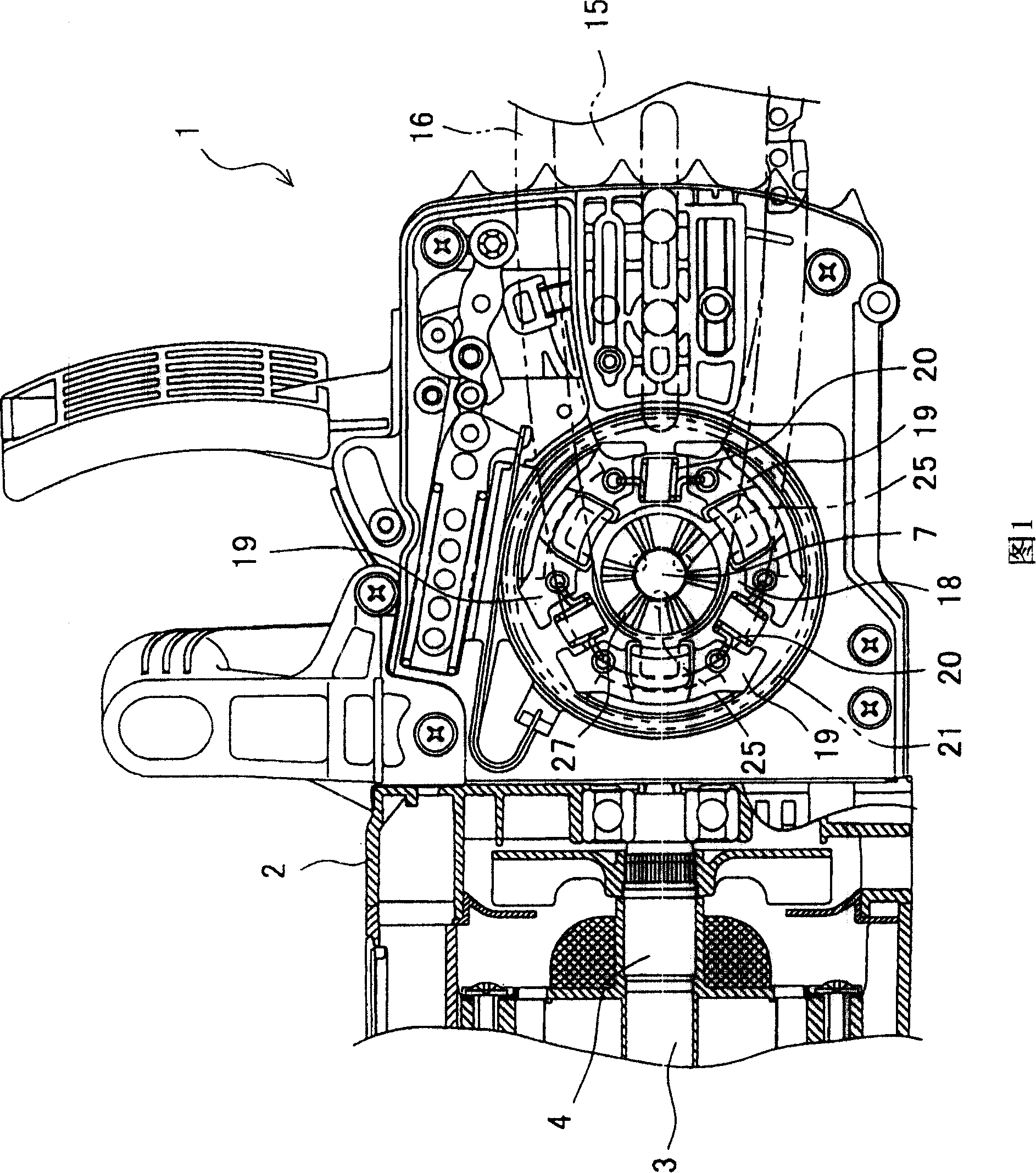
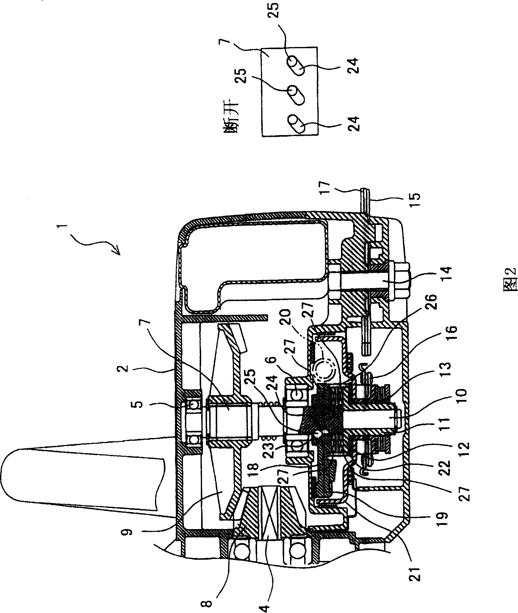
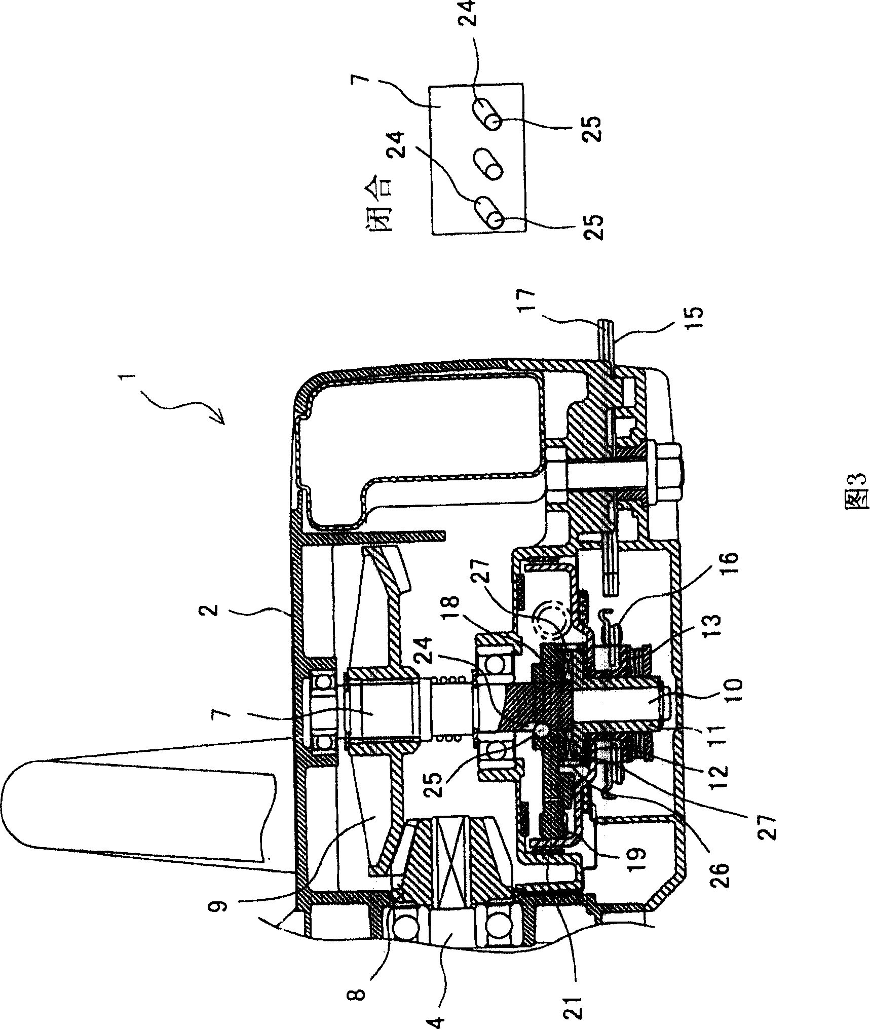
[0025] FIG. 1 is a partial vertical cross-sectional view showing an example of a chain saw, and the right side figure in FIG. 2 is a partial horizontal cross-sectional view. In the chain saw 1, the electric motor 3 is accommodated in the casing 2 facing forward (the right side in FIGS. The rotation of the output shaft 4 can be transmitted to the main shaft 7 by engaging the bevel gears 8 , 9 respectively fixed to the output shaft 4 and the main shaft 7 in a transverse direction perpendicular to the output shaft 4 . In addition, the end portion of the main shaft 7 on the opposite side to the bevel gear 9 protrudes laterally through the housing 2, and a cylindrical cam 11 that is independently rotatable is mounted on the protruding end portion 10, and the cam 11 is located on the inside. A flange 12 is extended (on the ball bearing 6 side), and a sprocket 13 integrally rotatable is fixe...


PUM


Abstract

The present invention provides a chain saw which can effectively shorten the braking time of a chain without using an electric brake. The composing of the chain saw is as follows: a centrifugal clutch (18) is externally fitted to a spindle (7), a cam (11) and a connecting body (21) are integrally provided with a sprocket (13), the cam (11) forming a cam teeth 27 at the centrifugal clutch (18) side, the connecting body (21) abutting with a weight member (19) of the centrifugal clutch (18). A same shaped cam teeth (27) are formed on the opposed surface to the cam (11) in the centrifugal clutch (18), a guide groove (24) inclined at a predetermined lead angle from the axial direction of the spindle (7) is provided on the outer peripheral surface of the spindle (7), and a connecting groove (23) is provided on the inner peripheral surface of the centrifugal clutch (18). A steel ball (25) is fitted between both grooves, and a coil spring (26) energizing the centrifugal clutch (18) to the direction departing from the cam (11) is provided between the centrifugal clutch (18) and a washer (22).

Description

technical field [0001] The invention relates to a chain saw, which is provided with a guide rod on a casing with a built-in motor, so that the chain rotates along the guide rod to cut the material to be cut. Background technique [0002] In the case of a chainsaw, in a housing having a motor driven by the closing operation of the trigger, the main shaft rotated by the motor is supported along a transverse shaft, and on the side of the housing, a motor that is rotated by the rotation of the main shaft is provided. A sprocket wheel and a flat guide bar protruding forward, and a chain is stretched between the sprocket wheel and the guide bar. Therefore, the rotation of the sprocket rotates the chain along the peripheral edge of the guide bar, whereby cutting materials such as logs can be cut. [0003] In this kind of chain saw, if the chain rotation caused by inertia is ignored after the trigger is turned off to stop the power supply to the motor, the material to be cut will b...

Claims


Application Information

Patent Timeline
Patent Type & Authority Patents(China)
IPC IPC(8): B27B17/02
CPCB27B17/083B27B17/10
Inventor 近藤雅树
Owner MAKITA CORP
Why Eureka
Try Eureka