Friction plate assembly, braking device and motor
A friction plate and brake technology, applied in the direction of brake types, brake actuators, brake components, etc., can solve the problems of brake braking performance failure, long brake response time, abnormal wear, etc., to reduce the actual braking time, The effect of improving work efficiency and reducing overall power
- Summary
- Abstract
- Description
- Claims
- Application Information
AI Technical Summary
Problems solved by technology
Method used
Image
Examples
Embodiment Construction
[0039] The motor in this embodiment includes a brake and a motor shaft.
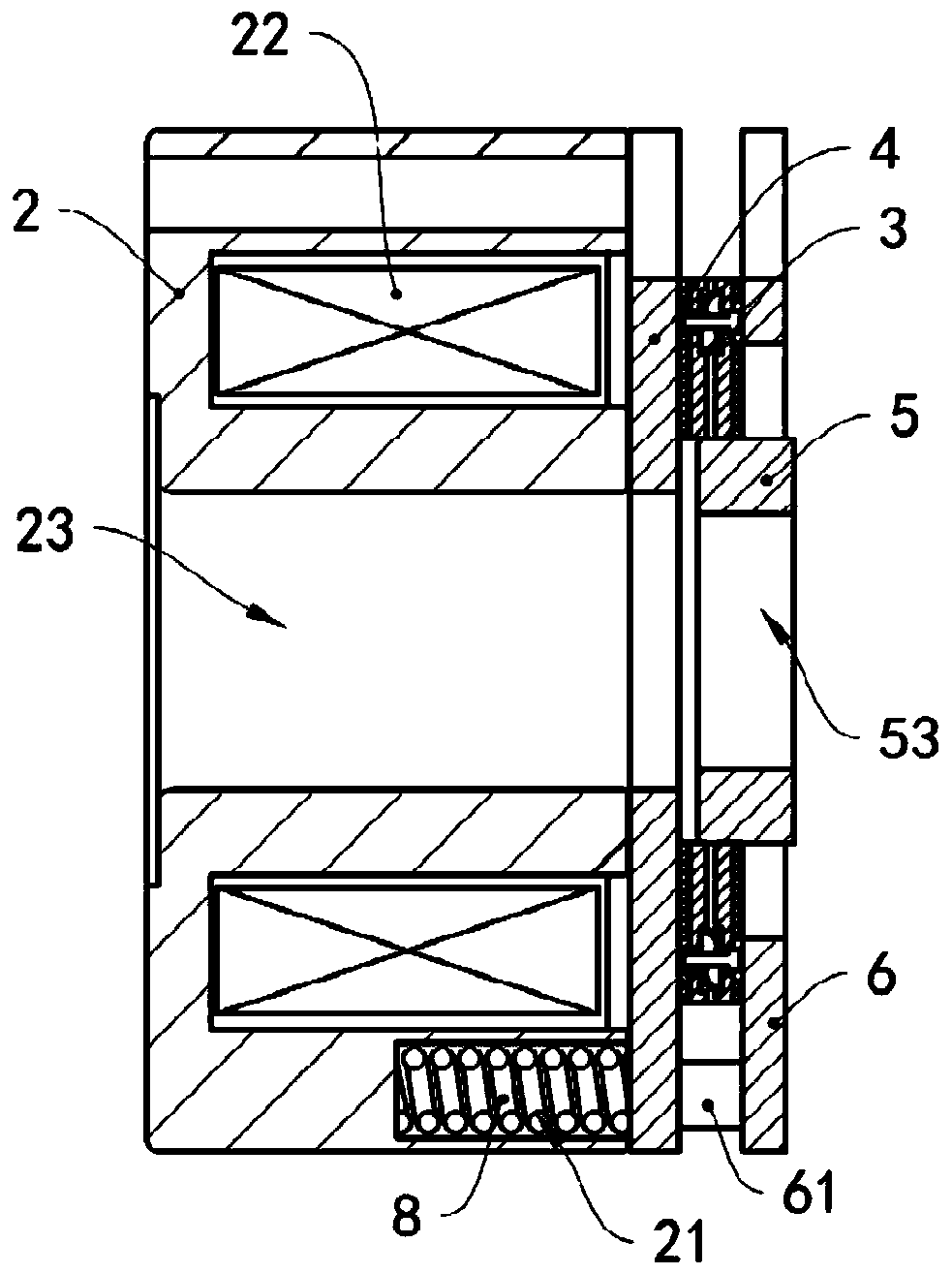
[0040] see image 3 , the brake includes a stator 2, a friction plate assembly 3, an armature 4, a square wheel 5, a baffle plate 6, and a second elastic member 7 ( Image 6 shown) and spring 8. One side of the baffle plate 6 is provided with a connecting column 61, one end of the connecting column 61 is fixedly connected to the baffle plate 6, the other end of the connecting column 61 is fixedly connected to the stator 2, the armature 4 is sleeved on the connecting column 61, and the armature 4 can be Sliding along the extension direction of the connecting column 61 , the friction plate assembly 3 is installed between the armature 4 and the baffle plate 6 . Stator 2 is provided with axle hole 23, and square wheel 5 is provided with fixing hole 53, and fixing hole 53 and axle hole 23 are coaxially arranged, and motor rotating shaft passes through axle hole 23 and fixing hole 53 successively, and motor ...
PUM
 Abstract
Description
Claims
Application Information
 - R&D
- Intellectual Property
- Life Sciences
- Materials
- Tech Scout
- Unparalleled Data Quality
- Higher Quality Content
- 60% Fewer Hallucinations
Browse by: Latest US Patents, China's latest patents, Technical Efficacy Thesaurus, Application Domain, Technology Topic, Popular Technical Reports.
© 2025 PatSnap. All rights reserved.Legal|Privacy policy|Modern Slavery Act Transparency Statement|Sitemap|About US| Contact US: help@patsnap.com


