Control device for hydraulic brake of mining dumper

A mining dump truck and control device technology, applied in the direction of hydraulic brake transmission device, etc., can solve the problems of difficult braking, disengagement, and longer braking time for the next time, so as to achieve convenient operation, reduce braking time, and structural simple effect

Inactive Publication Date: 2010-09-15
SANY MINING MACHINERY
View PDF5 Cites 6 Cited by
  • Summary
  • Abstract
  • Description
  • Claims
  • Application Information

AI Technical Summary

Problems solved by technology

However, in actual use, the brake device has a relatively large deficiency. When the brake is finished, the hydraulic fluid in the brake oil chamber is emptied, and the brake pressure is completely released, which makes each layer of brake pads separate, resulting in The next braking time becomes longer and braking becomes more difficult

Method used


Image

  • Control device for hydraulic brake of mining dumper
  • Control device for hydraulic brake of mining dumper

Examples


Embodiment 1

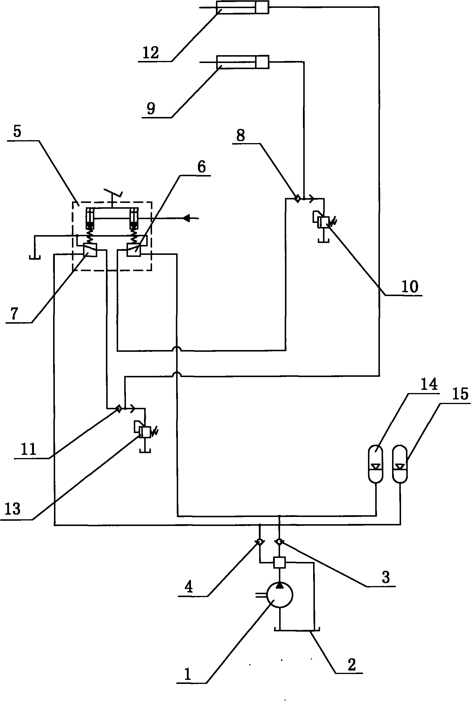
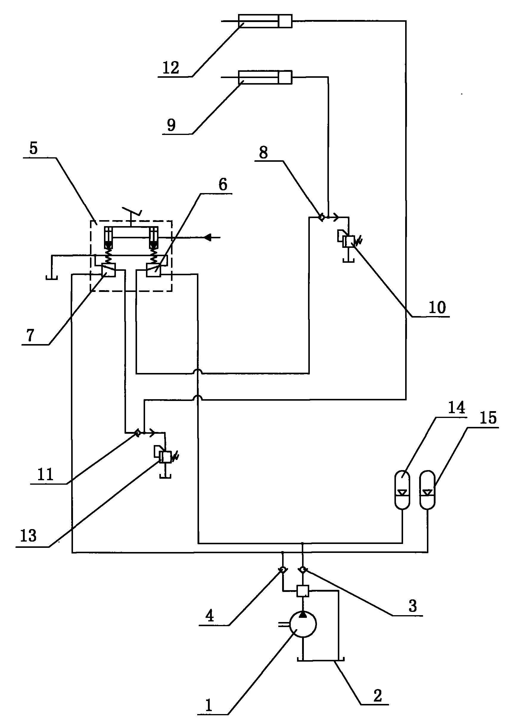
[0019] Embodiment one: see figure 1 As shown, a mining dump truck hydraulic braking device includes a hydraulic pump 1 and a fuel tank 2, the output port of the hydraulic pump 1 passes through the front wheel check valve 3 and the rear wheel check valve 4 respectively and the brake pedal The output ports of the brake pedal valve 5 are respectively connected with the front wheel brake 9 and the rear wheel brake 12, and the brake pedal valve 5 is respectively provided with a front wheel pilot pressure reducing valve 6 and a rear wheel pilot pressure reducing valve. pressure valve 7, the front wheel pilot decompression valve 6 is connected to the front wheel brake 9 through one input port of the front wheel shuttle valve 8, and the other input port of the front wheel shuttle valve 8 is also connected to the front wheel back pressure Valve 10; the rear wheel pilot pressure reducing valve 7 is connected to the rear wheel brake 12 through one input port of the rear wheel shuttle val...


PUM


Abstract

The invention discloses a control device for a hydraulic brake of a mining dumper. The control device comprises a hydraulic pump and an oil box, wherein the outlet of the hydraulic pump is connected with a braking pedal valve through a front wheel check valve and a rear-wheel check valve respectively; and the outlet of the braking pedal valve is respectively connected with a front wheel brake and a rear-wheel brake respectively. The control device is characterized in that a front wheel pilot reducing valve and a rear-wheel pilot reducing valve are respectively arranged in the braking pedal valve; the front wheel pilot reducing valve is connected with the front wheel brake through a front wheel shuttle valve, and the front wheel shuttle valve is also connected with a front wheel counterbalance valve; and the rear-wheel pilot reducing valve is connected with the rear-wheel brake through a rear-wheel shuttle valve, and the rear-wheel shuttle valve is also connected with a rear-wheel counterbalance valve. In the control device, the shuttle valves and the counterbalance valves are arranged between the braking pedal valve and the brake, so that certain oil pressure is maintained in the brake during braking removal, the next braking time is reduced, and the braking is quicker.

Description

technical field [0001] The invention relates to a hydraulic braking device, in particular to a mining dump truck hydraulic braking device. Background technique [0002] A dump truck is a vehicle that unloads goods by itself through hydraulic or mechanical lifting, also known as a dump truck. According to different driving modes, it is also divided into 6×4, 8×4 and semi-trailer dump trucks. According to different uses, it is also divided into ① mine dump truck, used to transport coal mines and sand; ② sanitation and green dump truck, used to transport garbage, etc. According to the direction of the compartment turning, there are also front-lift and side-turning dump trucks. [0003] Mining dump truck is a mining transport vehicle, which belongs to one of the mining equipment and is mainly used for the transportation of ore and other bulk materials in the mine. The mining dump truck is mainly composed of a frame, a cab installed on the frame, an engine, a gearbox, a brakin...

Claims


Application Information

Patent Timeline
Patent Type & Authority Applications(China)
IPC IPC(8): B60T11/24B60T11/28
Inventor 黄志怀张涛曹志春
Owner SANY MINING MACHINERY
Why Eureka
Try Eureka