
Method for deterring malicious network traffic

a network traffic and malicious technology, applied in the field of network security, can solve the problems of ineffective defending means, inability to protect end users, and inability to access data centers or data centers, and achieve the effect of effective and inexpensive methods

Inactive Publication Date: 2020-08-20
GO IDEA LTD
View PDF0 Cites 0 Cited by
  • Summary
  • Abstract
  • Description
  • Claims
  • Application Information

AI Technical Summary

Benefits of technology

The invention provides a way to prevent certain types of network traffic from outside users from entering data centers via the cloud. It achieves this by offering an efficient and effective method that is both cost-effective and precise in its deterrent actions.

Problems solved by technology

The defending means gets less efficient as it uses more models.
Thus, an attacker can finally paralyze the defending means, access to the data center or an end user.
Thus, the defending means gets less efficient and could be paralyzed.
However, this inevitably increases the cost in the defense.

Method used


Image

  • Method for deterring malicious network traffic
  • Method for deterring malicious network traffic
  • Method for deterring malicious network traffic

Examples


first embodiment

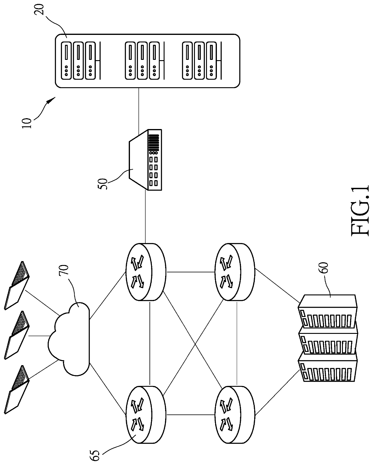
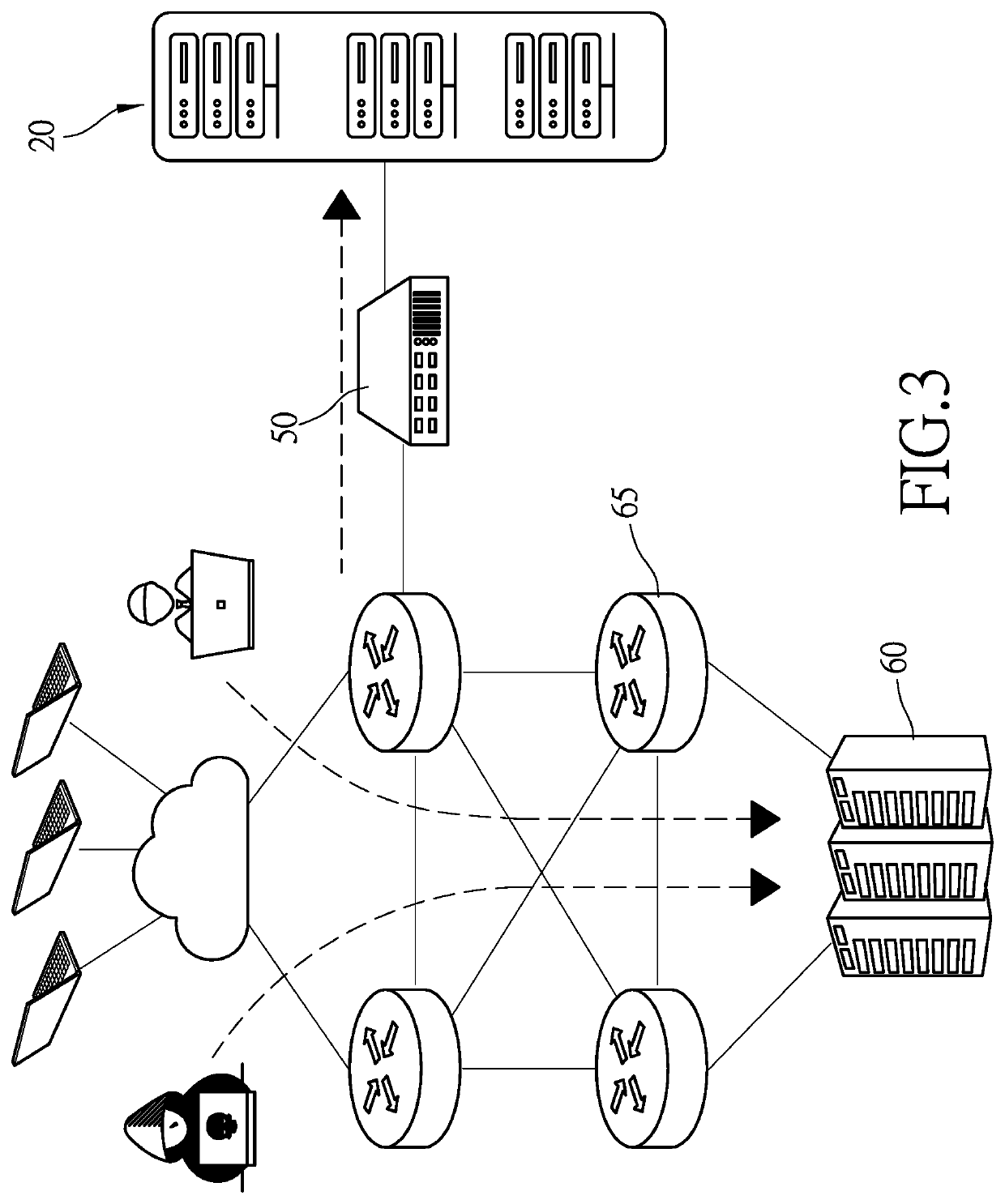
[0016]Referring to FIG. 1, there is shown a system for executing a method for deterring malicious network traffic according to the present invention. The system includes a data center 60 connected to a cloud 70 via multiple routers 65. A deterring apparatus 10 is used to detect whether network traffic into the data center 60 from the cloud 70 contain malicious packets. The deterring apparatus 10 includes at least one analyzer server 20 and a tap switch 50. The analyzer server 20 is connected to the system via the tap switch 50. Thus, the analyzer 20 executes deep packet inspection (‘DPI’) on packets of the network traffic heading for the data center 60 via the routers 65. On finding any of the packets of network traffic to contain any malicious pattern, the analyzer server 20 immediately provides a warning and / or blocks the network traffic.

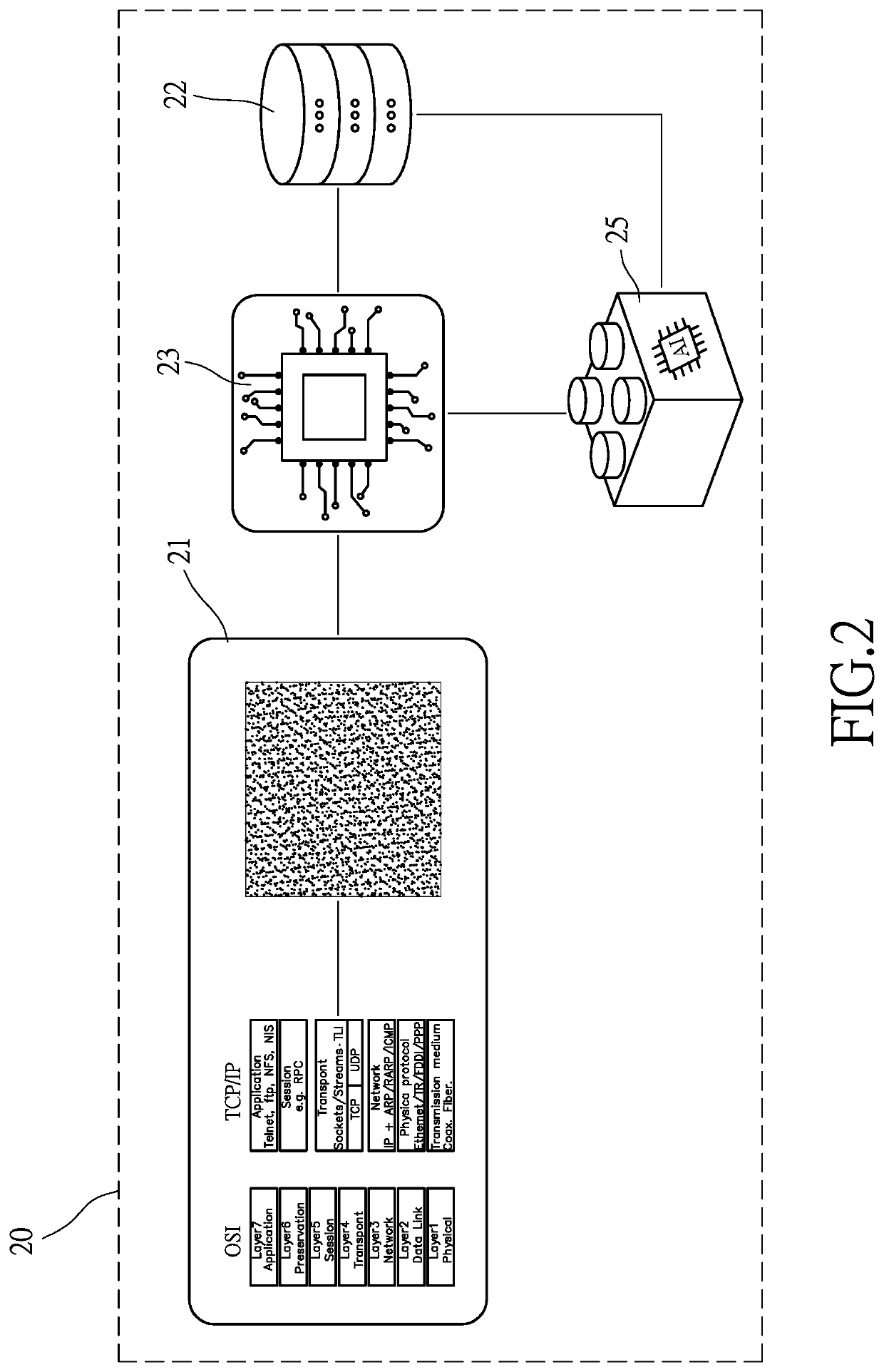
[0017]Referring to FIGS. 1 and 2, the analyzer server 20 includes at least one bitmap converter 21, at least one model-storing unit 22 and at lea...

second embodiment

[0031]Then, at S1032, the network traffic-related graphic is compared with at least one model-related graphic derived from at least one normal packet. The graphics processing unit 23 of the analyzer server 20 receives model-related graphics from the model-storing unit 22. Then, the graphics processing unit 23 compares the network traffic-related graphic with all the model-related graphics. In the second embodiment, the model-related graphics stored in the model-storing unit 22 are derived from known normal packets.

[0032]Then at S1042, it is determined whether the network traffic-related graphic matches any of the model-related graphics. The process goes to S1051 if the network traffic-related graphic does not match any model-related graphic, and goes to S1052 if the network traffic-related graphic matches any of the model-related graphics.

[0033]At S1051, a warning is provided or the packet of the inline network traffic is blocked. As mentioned above, the model-related graphics are d...


PUM


Abstract

A method for deterring malicious network traffic heading for a data center from an external user via a cloud includes the step of receiving at least one packet of inline network traffic before the data center. Then, the packet of the inline network traffic is converted into at least one network traffic-related graphic. Then, the network traffic-related graphic is compared with model-related graphics. Then, it is determined whether the network traffic-related graphic matches any of the model-related graphics. A warning is provided or the packet of the inline network traffic is blocked if the network traffic-related graphic matches any of the model-related graphics. The packet of the inline network traffic is transferred to the data center if the network traffic-related graphic does not match any of the model-related graphics.

Description

BACKGROUND OF INVENTION1. Field of Invention[0001]The present invention relates to security of a network and, more particularly, to a method for deterring malicious network traffic by using a graphic processing technique to inspect packets.2. Related Prior Art[0002]To protect a computer system or a network from attacks, the networks monitored and malicious network traffic is deterred by defending means such as a web application firewall (‘WAF’), an intrusion-preventing system (‘IPS’), an intrusion-detecting system (‘IDS’) and an advanced threat-preventing (‘ATP’) technique. A typical method to monitor the internet is use the defending means to execute deep packet inspection (‘DPI’) on packets of inline network traffic to a host computer or data center. On finding a packet to include malicious-pattern data, the defending means immediately provides a warning and / or blocks malicious network traffic.[0003]To inspect packets, packets of common attacks are analyzed, and malicious patterns...

Claims


Application Information

Patent Timeline
Patent Type & Authority Applications(United States)
IPC IPC(8): H04L29/06G06K9/62G06N3/08
CPCH04L63/0245H04L63/1416G06K9/6256H04L63/1425G06N3/08G06K9/6201G06F18/22G06F18/214
Inventor YEH, CHE-HUNGHUANG, JIAN-TINGLIN, YUEH-FENG
Owner GO IDEA LTD
Learn More